@csowada: Yes, that is sound advice. I used the HYT321 in a commercial project – it performs much better than the DHT22. But it is also way more expensive. If you need really exact values the DHT22 is the wrong sensor.
The DS18S20 allows for multiple sensor on the same wire. Have you tried this configuration?
I will build your board next month, once I get back my electronic play space. This design is really neat.
You’re lucky ![]() I implemented this in the last four commits.
I implemented this in the last four commits.
The code works like this: At compile time you define how many DS18S20 you have on your bus (I tested up to four). During startup, the appropriate number of REST endpoints is created, i.e. /temperature/0 maps on the first sensor, /temperature/1 on the second and so on. During runtime the measurement routine just enumerates the devices on the bus.
I wanted to add a 304 redirect for the old /temperature endpoint to the first sensor before announcing it here, but if you keep in mind that the current master has a different semantic than described previously the functionality should already be there.
HTH,
-Mathias
I finally had some soldering time available and created a breakout board for the ESP-WROOM-02 modules. They are meant to be soldered directly onto a PCB, but for prototyping I prefer a more modular approach. This is what I came up with:

As with my ESP-01 prototyping setup I have a development board that I can use to connect a breadboard to the ESP module. The ESP modules themselves have 50mil connectors, so I had to create a little adaptor for them. Turns out its rather easy to solder this if you stick to a sequence that reduces the heat during soldering. I thought I would share my approach. I’m soldering the final 3V3 connector in the sequence below:
(0) Hotglue the ESP-WROOM-02 upside down to a piece of perfboard and solder pinheaders on both sides. This is a closeup of the finished module:

(1) Add some solder to the pinheader.

(2) Connect the silver-plated copper wire to the pinheader just by adding some heat with the soldering iron.

(3) Then solder the wire to the ESP board. Make sure to leave the wire uncut! It acts as a heat sink, otherwise the pinheader joint heats up too fast and the wire comes loose. After everything is soldered cut off the excess wire. The result should look like this:

Leaving as much wire as possible to act as a heat sink was the key to produce these little boards ![]() My sensor code is already running on this setup, hopefully I will be able to finish a multi-sensor onewire installation tomorrow.
My sensor code is already running on this setup, hopefully I will be able to finish a multi-sensor onewire installation tomorrow.
Quick update: my new board with three DS18S20 sensors is up and running. It is currently monitoring my heating system:

I think there is some optimization to be done ![]()
The documentation of my hardware along with the new code for dealing with more than one DS18S20 is now on github. I also added the ESP-WROOM-02 to the schematic:

This is a nice little board that I will use in the future. It is basically a drop-in replacement for the ESP-1 that offers more pins. It is also slightly more compact. Maybe I will manufacture a proper PCB for this setup.
3 Likes
Amazing project! I’ll try it as soon as I get some spare time. Which sensor gives better accuracy? DS18S20 or DHT22? Thanks.
If you mean temperature measurements: The DS18S20 is rather exact, the DHT22 not so much ![]()
Hi
I am interested in making a similar project. I have 6 heating sones in my flat, currently I have a relay connected to openhab which is running on my rpi. This switches on this thermostat at 6 am and off at midnight. However i would rather like to make my own thermostat. So my idea is to take these sensor:
esp8266 - wifi main CPU
DHT22 temperature sensor air sensor
1 wire temperature sensor for under floor
acs712-current-sensor
10A relay (230V*10A=2300W)
CO2 sensor(optional)
Power supply
Light sensor(optional)
The problem is that all need to fit inside this junction box.
Would anyone do it this way? The CO2 sensor are to controll the ventilation and the light sensor to control lights.
Thanks! And how many days has the circuit been running continuously for? I mean I’d like to know how reliable is the board with your code, not talking about measures which is clear to me.
I think I deployed the first sensor a few days before writing the first post - so 10th of september would be a fair estimate. No problems so far.
Thanks, you totally deserve my star on github.
@skatun: As I mentioned above I use external wall-wart power supplies. My PCB is around 5x5cm. If you choose a compact power supply it should be possible to squeeze everything in. BUT: If you’re measuring temperature you want to ensure good ventilation of the measurement area - which I doubt is possible within this enclosure. I would recommend to put the sensors on wires and expose them directly to fresh air.
HTH,
-Mathias
Cant that be compensated for in the software?
Which sensors would you recommend to add to the sensor unit?
No, withou air circulation, you cannot compensate. You can only measure the air temperature inside the enclosure, but that will not necessarily correlate to the room temperature.
As for the sensors: I’m unsure what you mean.
Well the enclosure is not 100% air tight, and you would ideally meassure temperature somewhat 1m from the wall(enclosure), in addition the electronics produce heat. So if I take my Netatmo temperature sensor and place it 1 meter from the wall, then log the output from dht22 for different temperatures in the range 15 -25C and then calibrate to fit the data from netatmo,I think it would stay calibrated over time. Or am I missing something here?
Do you think these sensor would be nice to add to the sensor unit, (fill up the space in the enclosure)[quote=“skatun, post:28, topic:2746”]
esp8266 - wifi main CPUDHT22 temperature sensor air sensor1 wire temperature sensor for under flooracs712-current-sensor10A relay (230V*10A=2300W)CO2 sensor(optional)Power supplyLight sensor(optional)
[/quote]
I remember reading some where that the DHT22 isn’t as accurate when running at 3.3V compared to 5V.
This is ideal for sensors https://www.wemos.cc/product
1 Like
The DHT22 is quite stable for me…
Nice work! This was the inspiration.
I am using the WeMos D1 mini with DHT11 shield and the NodeMCU firmware.
A few lines of LUA code and I have rough temperature and humidity readings sent to openHAB every 30 seconds.
Hello,
I like to share some experiences with my DIY Sensors.
First I use the “ESPeasy” firmware which supports a lot of Sensors and all communication over MQTT. No coding nessesary, easy to use web interface and even some simple local rules and communications between the nodes is possible. For everybody who is looking for an easy to use firmware:
http://www.esp8266.nu/index.php/Main_Page
Great and supportive community too.
The DHT11 / 22 is really outdated. I use the BME / BMP 280 from Bosch, you can get it even cheaper than the DHT22 from china on a easy to connect module. The Sensor is really amazing (measuring pressure in an accuracy to detect level changes of around 75cm!. So be aware when you slam the doors ![]() No filering nessesary. A WeMos shield with the BME 280 whould be perfect.Using the I2C Bus it whould be really “stackable”
No filering nessesary. A WeMos shield with the BME 280 whould be perfect.Using the I2C Bus it whould be really “stackable”

For Light I use the BH1750. Much better than a photo resistor.

And for a little bit Fun a OLED display. Put all on a breadboard in 30 minutes including “coding” and power it over the nodeMCU regulator and you get your values and send commands via MQTT.
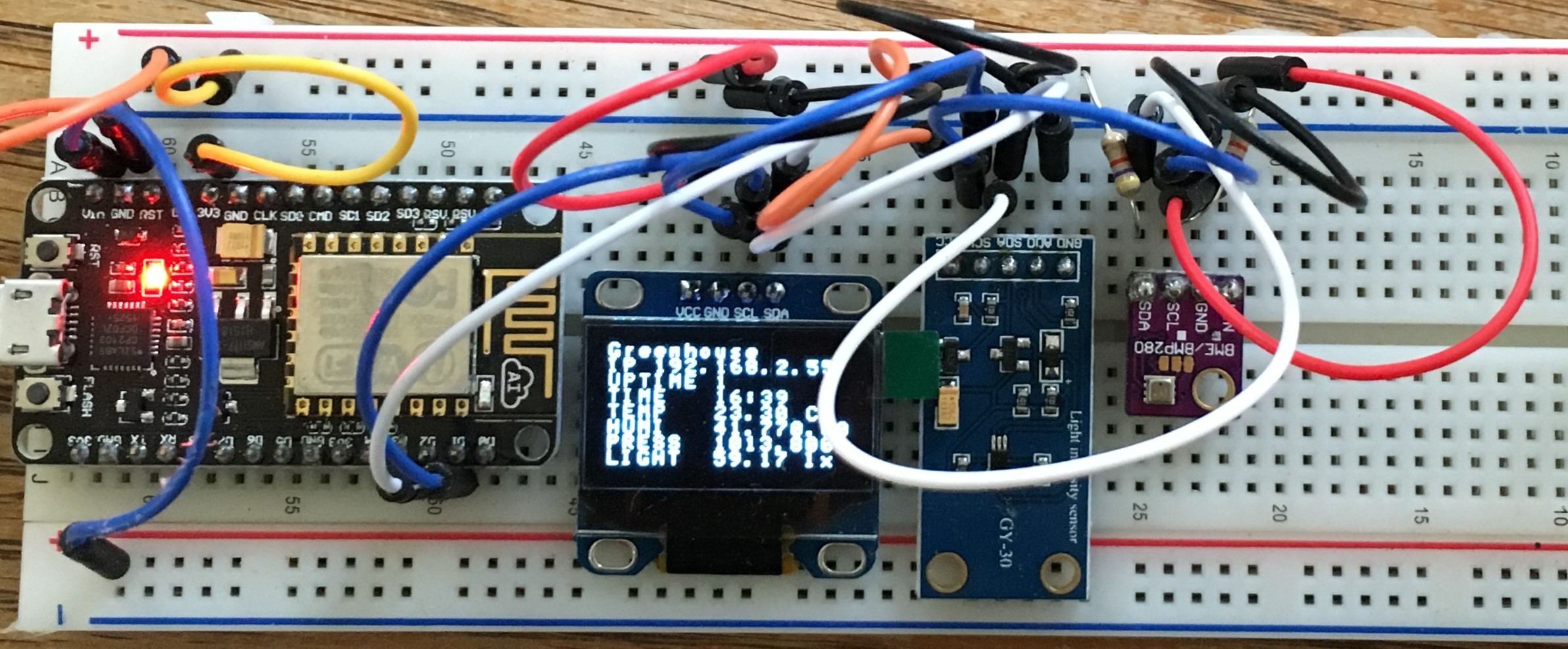
All sensors running on I2C bus. A I2C bus scanner is integrated so hardware debugging is easy too.
To integrate it inside a wall mount I will use this little module. for around 20€ it solves the size and power supply issue. (you can find it on ebay - I know two different designs available in germany.) I will give you an update when done. - Mess arount with mains power @ your own risk!!!

ESPeasy support deep sleep too so I plan to run a sensor on Li-Ion as soon as possibe.
I use it to controll an electric heater in my greenhouse (Relay not shown on the picture). Working perfect. Next step is to measure the energy. But measuring AC current is not so easy …
Chris
4 Likes