New binding - Rego 6xx based heat pumps

Nice :wink:

Almost what I have…the only difference is that i have my +5v source for TX018E side B coming from the RPI, as it can supply both +3 and +5. Do you think i should really be sourcing that from the D9 of the Rego? Might be safer!

Pete

A bit modified diagram, based on a quick look into the datasheet:

My suggestion would be to separate rego and rpi side as much as possible, in your case only keep GND connected together, both 7400 and TXS0108E’s B side should be powered by the rego unit (+5V). As you can see from the diagram, I’d say you don’t need to connect resistors to power supply pins as you described (nor I found any evidence within the datasheet that they might be needed). There only should be a pull down resistor on the OE pin so outputs are enabled when power supply is stable.

That are my two cents, won’t bother you anymore with suggestions, but wouldn’t like that anything happens to your controller unit (nor there is any guarantee that my suggestions are 100% safe :confused:).

Really appreciate the suggestions. These are expensive bits of kit, so anything I can do to make double-sure it’s ok is a bonus - so thanks!

I think keeping the Pi and Rego sides completely separate is a good shout. Will tune.

Am so glad I have got this going with my prototype board. Will need to do something more robust, but have had fun so far!

Have updated my hardware to use the +5v side for components connected to the Rego and +3v side from connections to the rpi. So I’ve isolated them, so hopefully thats a bit safer and will protect my rpi and Rego.

Gone through all the item mappings, here what I have now…

useful data mappings you have implemented here, great stuff.

Couple of things to clarify…

What’s the difference between frontPanel#alarmLamp and deviceValues#alarm ?

I think ‘Switch Valve’ will be on when generating hot water, but I would like to know if it is supplying underfloor heating or DHW. Is there a way to tell this, it’s a 3 way valve I think (off, DHW only, Heating only, both) Could this be something to do with Switch Valve 2?

Don’t think I use the others that are not mapped, but will keep you up to date with my working.

I’ve managed to get the real-time status of each of these values for now, but I’ll be wanting to log some history and produce some graphs, esp the temps. Any recommendations on the best way to do this? I guess I should keep request interval to 60 seconds, that should be accurate enough.

Actually, just read the openHab section on persistance, so i need to decide what method i want to use to store the data. I’ve also got an OpenEnergyMonitor which has a very good series data store in https://emoncms.org Am already using to log electricity consumption and has some great graphs / widgets, think it can receive MQTT messages there. May try that.

Glad to hear it is working!

Regarding wiring - I’m curious, did you remove the resistors on 3v/5v inputs? Or do you still need them?

Yes, there are a lot of channels that a rego 6xx unit provides, I shared a link in my previous posts, where you can see all. As pointed out, some channels might not be available for your heat pump, depending on your model and setup, while others provide info that is not interesting or just too static - up to you to add those that you see fit :slight_smile:

What’s the difference between frontPanel#alarmLamp and deviceValues#alarm ?

I’m not 100% sure, I believe both provide same information coming from different registers… The frontPanel# ones are actually one to one mapping between the lights you have on your heat pump’s front pannel:

  • heat pump
  • additional heat
  • hot water (DHW)
  • alarm

The “Switch Valve” is actually a 2 way valve and can either heat DHW or heating water, so only two states are possible; if both are needed, DHW has priority over heating water (i.e. floor heating). I have a mapping in place where in one case I see:

when switch valve is in position of heating water (i.e. floor heating) or:

when switch value is set to heat DHW.

For completeness, please see my setup (iPhone client, screens stitched together):

I can share my .items file for reference, please let me know.

I use InfluxDB and Grafana for storing data, it is really powerful and easy to use, there is also a great tutorial on hot to set it up.

I have a 30 seconds refresh interval in place, running for a couple of months without any problems, sample grafana chart can be seen here also:

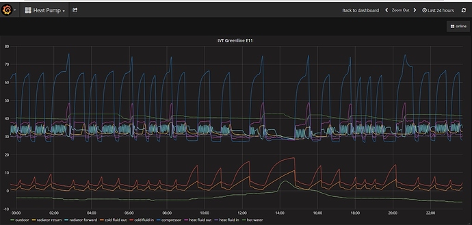
Lastly, looking into provided screenshot, switch valve 2 and compressor speed are not available for rego 6xx units, please see list of supported channels.

Also, the cold fluid out value looks a bit strange - 67.9? Do you have it mapped correctly?

Thanks for this. Like your graphs. I’ll give InfluxDB a try.

I kept the resistors on, as when i took them off I started to get noise again - lots of extra data.

I’ll review your link again with the list of channels, just to see if there are any other interesting data points I can get from my Greenstore.

If you wouldn’t mind sharing your .items file that would be good. I’d like to see how you’ve setup your Switch Valves. Mine currently just says ‘on’ or ‘off’ - maybe i need to change the item type.

I’m going to double-check my cold fluid values and mapping. They do look really high. Will report back.

I have a mapping in place within the .sitemap file for the switch value:

Text label="Switch valve [Heating water]" icon="radiator" visibility=[regoheatpump_ipRego6xx_ivt_deviceValues_switchValve == OFF]
Text label="Switch valve [Hot water]" icon="faucet" visibility=[regoheatpump_ipRego6xx_ivt_deviceValues_switchValve == ON]

to map on/off values.

A quick word on my setup - I have no .items or .thing file in place, only the .sitemap. Things and channels are setup as following:

  • first set “simple mode” to on within PaperUI | Configuration | System | Item Linking and hit Save,
  • add the rego thing within the PaperUI, make sure to set thing Id to some string, I use “ivt”,
  • add channels

Using this approach you now have a list of channels setup and they seem to have the following naming convention:

<binding>_<thing>_<thingid>_<group>_<channel>

I use the ipRego6xx thing and “ivt” as the thing id, as described above, so using above approach, I get a list of channels:

regoheatpump_ipRego6xx_ivt_sensorValues_outdoor,
regoheatpump_ipRego6xx_ivt_sensorValues_externalHotWater,
regoheatpump_ipRego6xx_ivt_sensorValues_radiatorReturn,
...

and than I use those in the sitemap:

sitemap house label="House" {
	Frame {
		Text label="IVT Greenline E11" item=regoheatpump_ipRego6xx_ivt_sensorValues_outdoor icon="boiler_viessmann" {
			Frame label="Sensor Values" {
				Text item=regoheatpump_ipRego6xx_ivt_sensorValues_outdoor
				Text item=regoheatpump_ipRego6xx_ivt_sensorValues_externalHotWater
				Text item=regoheatpump_ipRego6xx_ivt_sensorValues_radiatorReturn
				Text item=regoheatpump_ipRego6xx_ivt_sensorValues_radiatorForward
				Text item=regoheatpump_ipRego6xx_ivt_sensorValues_compressor
				Text item=regoheatpump_ipRego6xx_ivt_sensorValues_heatFluidOut
				Text item=regoheatpump_ipRego6xx_ivt_sensorValues_heatFluidIn
				Text item=regoheatpump_ipRego6xx_ivt_sensorValues_coldFluidOut
				Text item=regoheatpump_ipRego6xx_ivt_sensorValues_coldFluidIn
				Text label="Charts" icon="line" {
					Frame {
						Switch item=Combo_From_HP_Charts mappings=[6HOUR="6 Hours", 12HOUR="12 Hours", DAY="Day", WEEK="Week"]
						Image visibility=[Combo_From_HP_Charts == 6HOUR] refresh=60000 url="http://localhost:3000/render/dashboard-solo/db/heat-pump?panelId=1&width=600&height=300&from=now-6h&to=now&theme=light"
						Image visibility=[Combo_From_HP_Charts == 12HOUR] refresh=300000 url="http://localhost:3000/render/dashboard-solo/db/heat-pump?panelId=1&width=600&height=300&from=now-12h&to=now&theme=light"
						Image visibility=[Combo_From_HP_Charts == DAY] refresh=3000000 url="http://localhost:3000/render/dashboard-solo/db/heat-pump?panelId=1&width=600&height=300&from=now-1d&to=now&theme=light"
						Image visibility=[Combo_From_HP_Charts == WEEK] refresh=300000 url="http://localhost:3000/render/dashboard-solo/db/heat-pump?panelId=1&width=600&height=300&from=now-1w&to=now&theme=light"
					}
				}
			}
			Frame label="Control data" {
				Text item=regoheatpump_ipRego6xx_ivt_controlData_radiatorReturnTarget
				Text item=regoheatpump_ipRego6xx_ivt_controlData_radiatorReturnOn
				Text item=regoheatpump_ipRego6xx_ivt_controlData_radiatorReturnOff
				Text item=regoheatpump_ipRego6xx_ivt_controlData_radiatorForwardTarget
				Text item=regoheatpump_ipRego6xx_ivt_controlData_addHeatPower
			}
			Frame label="Device values" {
				Text item=regoheatpump_ipRego6xx_ivt_deviceValues_radiatorPump
				Text item=regoheatpump_ipRego6xx_ivt_deviceValues_heatFluidPump
				Text item=regoheatpump_ipRego6xx_ivt_deviceValues_coldFluidPump
				Text item=regoheatpump_ipRego6xx_ivt_deviceValues_compressor
				Text item=regoheatpump_ipRego6xx_ivt_deviceValues_additionalHeat3kW
				Text item=regoheatpump_ipRego6xx_ivt_deviceValues_additionalHeat6kW
				Text item=regoheatpump_ipRego6xx_ivt_deviceValues_alarm
				Text label="Switch valve [Heating water]" icon="radiator" visibility=[regoheatpump_ipRego6xx_ivt_deviceValues_switchValve == OFF]
				Text label="Switch valve [Hot water]" icon="faucet" visibility=[regoheatpump_ipRego6xx_ivt_deviceValues_switchValve == ON]
			}
			Frame label="Front Panel" {
				Text item=regoheatpump_ipRego6xx_ivt_frontPanel_heatPumpLamp
				Text item=regoheatpump_ipRego6xx_ivt_frontPanel_additionalHeatLamp
				Text item=regoheatpump_ipRego6xx_ivt_frontPanel_hotWaterLamp
				Text item=regoheatpump_ipRego6xx_ivt_frontPanel_alarmLamp
			}
			Frame label="Status" {
				Text item=regoheatpump_ipRego6xx_ivt_status_lastErrorTimestamp
				Text item=regoheatpump_ipRego6xx_ivt_status_lastErrorType
			}
		}
	}
}

I used this approach a lot when developing the binding when I was adding/removing the thing a lot. If you use i.e. “bosch” as your thing id, you should have something like this:

regoheatpump_serialRego6xx_bosch_sensorValues_outdoor

This way you can (more or less) easily add/remove the thing using PaperUI while have the same .sitemap - in case of course you need to do so in the first place :slight_smile:

Great, thanks for sharing. This is really helping.

I’ve got the Switch Valve working. I think I’ll also add an extra piece of logic so it doesn’t display at all if the heat pump is not generating heat. ie, not producing hot water or heating water.

Have also got InfluxDB and Grafana up and running, going to capture some data tonight/tomorrow.

Will report back!

On the ColdFluidOut value, its still really high. Just looked in the logs, and that’s what’s coming from the heat pump…

2017-06-09 05:13:40.171 [DEBUG] [tpump.handler.Rego6xxHeatPumpHandler] - Got value for 'sensorValues#coldFluidOut' = 833

Just checked the temps front panel of my heat pump, and it is dsplaying:

Heat TrFluid Out (GT8) 83.3
Heat TrFluid In (G9) 15.2

If I look at the history in Grafana, ColdFluidOut looks to remain between 81 and 84 all night

Do you think my heat pump is running way too hot? (not really an OpenHab question!)

Lets start with a disclaimer - I’m no heat pump expert :slight_smile: , but my understanding is:

Cold fluid in/out - this is the temperature in medium where heat pump is taking temperature/energy from - i.e. in ground collector. In/out are referenced from the heat pump:

  • cold fluid in (GT10) = fluid temperature coming into the heat pump,
  • cold fluid out (GT11) = fluid temperature coming from the heat pump

So when heat pump is operating, the cold fluid in should have a bit higher value (temperature) as the one coming from the heat pump.

On the other hand, the heat fluid in/out is the temperature in medium (fluid) that heats your DHW or floor heating (depends on the switch valve). In/out are again referenced from the heat pump:

  • heat fluid out (GT8) = fluid coming from the heat pump,
  • heat fluid in (GT9) = fluid coming back to the heat pump

Naturally, when heat pump is operating, heat fluid out has slightly higher temperature than when it returns.

Your mapping should be like this:

  • GT1 = sensorValues#radiatorReturn,
  • GT2 = sensorValues#outdoor,
  • GT3 = sensorValues#externalHotWater,
  • GT6 = sensorValues#compressor,
  • GT8 = sensorValues#heatFluidOut,
  • GT9 = sensorValues#heatFluidIn,
  • GT10 = sensorValues#coldFluidIn,
  • GT11 = sensorValues#coldFluidOut

Heat TrFluid Out (GT8) 83.3
Heat TrFluid In (G9) 15.2

As you can see from above mapping, this is related to the “heat transfer fluid”, while the value:

2017-06-09 05:13:40.171 [DEBUG] [tpump.handler.Rego6xxHeatPumpHandler] - Got value for ‘sensorValues#coldFluidOut’ = 833

is referencing the “cold” fluid circuit - sensorValues#coldFluidOut = GT11.

Can you please double check values displayed directly on your heat pump (GTx) and based on the above mapping check that values match? I.e.

GT1 (heat pump display) = sensorValues#radiatorReturn (OH2 displayed value)

I’ve actually got some external temperature probes on my flow and return pipes from my in ground collectors, just next to the heat pump itself. I’m monitoring these separately. Obviously there will be some heat loss/gain. But when the pump is in operation these are showing a difference of about 4Deg - which i think is about right. Usually 8Deg / 12Deg.

Will check my front display again.

btw…here are my charts showing a period when the heat pump was on and feeding the domestic hot water…

Got a nice smooth line on the compressor temp, but why are the other temps displayed as they are?

I have setting in the config file very similar:

CompressorTemp, HeatingReturn   : strategy = everyChange, everyMinute
HeatFluidIn,HeatFluidOut        : strategy = everyChange, everyMinute
ColdFluidIn,ColdFluidOut        : strategy = everyChange, everyMinute

Checked the front panel again, sorry got the wrong GT number…(have to run into my back boiler room!). Here are the temps from the front panel with current values:

GT8 - Heat tr fluid out GT8 = 25Deg
GT9 - Heat tr fluid in GT9 = 25Deg
GT10 - Ht trfld(coll) in = 12Deg
GT11 - Ht trfld(coll) out GT11 = 82Deg

Here’s my mapping in things…

And here’s the descriptions from the documentation…

It looks like the 80Deg value is just wrong - on the heat pump display and the feed i’m getting. wonder if the temp probe is faulty? As i would only expect the difference between GT10 and GT11 to be 4-5degC. Just a thought

I meant if you compare values displayed on the heat pump and those displayed within i.e. Basic UI - do they match? Seems like they do…

GT11 - Ht trfld(coll) out GT11 = 82Deg

That one looks way off, my readings are usually a couple of degrees apart (cold in/out), as you described above. I would expect it to be less than GT10… But I guess this has nothing to do with the OH2 or binding :slight_smile:

My charts do look smooth for all plotted values, as you can see on the image I shared a couple of posts back. When I come home I can provide the Grafana config… And if I remember well, I think I store changes to the database on every change (as you do) and on every hour, but that shouldn’t have any effect on the chart you see…

If you attach to the InfluxDB using console (or any other tool), or if you display them in a table - do the “raw” values stored there make sense?

As a side note - I configured InfluxDB so it stores data on an external USB drive, attached directly to my rpi in order to extend the life of the memory card…

I’m now convinced the 80Deg value is a faulty temp sensor. Will need to look at the heat pump itself. Thanks for helping to investigate!

On InfluxDb…

Yea, i saw your charts looked very smooth, that’s why i thought mine were weird. Will check out the raw data.

Good idea on the external drive, keeps it all separate too…am sure the’ll be a lot of data at that rate!

Just an update on the SwitchValve settings…

I’ve added a rule to only display the SwitchValve status when the heat pump is actually on. Had to create a rules file in the rules config directory…

Define a dummy variable in your .items file

switch SwitchValveVisibility

Create a rules file in [config]/rules (i used heatpump.rules}

rule "Set HeatPump Switch Valve Flag"
when
    Item SwitchValve updated or
    Item HeatPumpOn updated
then
    if(HeatPumpOn == OFF) SwitchValveVisibility.sendCommand(OFF)
    else
    {
    if(SwitchValve == ON) SwitchValveVisibility.sendCommand(WATER)
    else SwitchValveVisibility.sendCommand(HEATING)
    }
end

Then add the following lines to your sitemap:

Text label="Switch valve [OFF]" icon="pump" visibility=[HeatPumpOn == OFF]
Text label="Switch valve [Underfloor Heating]" icon="flow" visibility=[SwitchValveVisibility == HEATING]
Text label="Switch valve [Hot water]" icon="faucet" visibility=[SwitchValveVisibility == WATER]

…had to do a rule as you can’t do AND logic in the sitemap file. Bit more complex, but I got there!

On the Grafana ‘smooth lines’ issue …i was zoomed in too far, if i zoom out a little the lines all become smooth.

Actually, now solved the ‘smooth lines’ issue in Grafana. I had the wrong ‘fill’ settings in groupBy. Should be fill(none) and i had fill(null). Looks fine now…

Yes, I too have it set to - fill(none). Seems like your setup is working fine now :stuck_out_tongue: