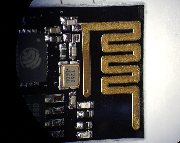
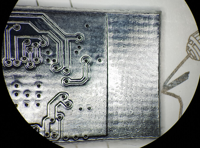
ESP8266 Antenna Mod - extend WiFi range

Howdy!

I was watching this video from one of my favourite makers on YouTube when I came across the following point in the video:

It looks like an ESP8266 but it’s not. It’s an NRF24L01 module, which is a 2.4 GHz communications module. Nevertheless, 2.4 GHz is 2.4 GHz, and this thing has antenna wires soldered onto it!

I’ve had problems with the WiFi range on the ESP8266. I’ve seen at least three distinct PCB antenna types. I’ve not been able to find anyone else making reference to these different types and how they perform, so here is my own anecdotal evidence.

In descending order of performance: Most sensitive, Bad, Awful.

The design to the left seems best by far. It also appears to have nearly twice the active area on the circuit board.

But, here’s the fun part. It never occured to me that I could simply cut the circuit board traces and solder my own wires on there as antennas!

I’ve done it and literally seen 10 dB signal improvement. Every 3dB is equivalent to a doubling of power, so 10dB is actually ten times the effective power. Marginal locations suddenly work flawlessly.

At first I used CAT5 networking wire strands, then once I examined it under the microscope and found that it looked like I had soldered freaking timber logs to the circuit board, I realized that 30 AWG wire-wrapping wire would be a better fit.

Here are some microscope photos of the process of modifying an ESP-01. Please note that I’m a novice at this, still learning the tools, so it’s not pretty… but it works like a charm.

Unmodified front:

Unmodified rear:

After some butchering with a utility knife:


58mm 30 AWG wires soldered on:


In the case of a NodeMCU board, which have the ESP-12 module directly mounted, there’s no easy access to the rear for the ground plane wire. In those cases, I’ve found that adding just an antenna wire without adding a ground wire is still worthwhile and did improve reception for me.

I used this online antenna length calculator to arrive at 58 millimeters, based on an entered frequency of 2450 MHz.

5 Likes

Why cut the on board antenna only to fill it back in with solder? Doesn’t that essentially repair the cut?

It’s not actually filled with solder, there’s just solder on both sides of the cut. I tried showing it in the photo but it doesn’t show as clearly in photos as it did in real life, probably due to the lack of depth. Looking directly into the binocular microscope there was plenty of clearance. :slight_smile:

:+1:

Here’s wishing I had a binocular microscope. :smiley:

2 Likes

I figured I would need one to work on any circuit board with surface mount components.

It can get expensive watching makers on youtube.

This is the one I have, after seeing it in this video.

It’s actually trinocular (binocular + camera port). I bought this camera, but it’s utter garbage:
Dim, noisy, narrow image.

The images I posted in this thread were actually taken by holding my phone in front of one of the eyepieces!

Maybe I should get a better camera (since that one is unusable) but I’m not sure which one, and they’re kinda too expensive to take a chance.

This one claims to have a sony sensor but it’s almost $500 bucks… that seems crazy to me in this day and age, considering that’s what the entire trinocular microscope was, how can a lens-less camera be so expensive?

Nice information thank you ! But could you show a picture how you place the wires after soldering them, where does the ground wire go in regards to the transmit wire? are they oriented like a dipole antenna like in the first picture of the NRF module?

A simple way of extending range is to use a HomePlug wireless access point. This plugs into a mains socket where you need to extend your wireless network to. You need a second, normal HomePlug adaptor connected to your router via Ethernet.

Yes, exactly like that dipole (just pointing in opposite directions) although in some cases I had to bend them due to space constraints. As long as ground and signal are as far away from each other as possible, it seems to work.

1 Like

Great improvement with Wemos D1 board! -76dBm -> -62dBm within the same conditions (placement etc.). Thank you for the idea!

1 Like

Worked for me, Thanks!

The range wasn’t increased by that much vs stock, but it’s a mod that only takes a few minutes so why not.

Why do we have to cut the existing circuit, why can’t we attach the wire at the end of the gold plated connection?

That’s not a gold plated connection, that’s the antenna. If you attach a wire to it, you’re attaching an antenna to another antenna, and the result certainly will no longer be tuned for the desired 2.4 GHz frequency.

1 Like

Hello

so first of all…if you cut the trace on top (which you should) then attach a piece of wire…you have a mono-pole antenna. You dont need to cut underside.

If you are using a coax or 2 pair of wire, you will need to attach the ground

Also invest in a decent multimeter. When you do check conections etc you will find that the antenea on the 8266 has a via (u can look that up) that connects to ground on the straight portion of the top side of the antenea.

have fun

you can look up the file for this type of antenea. search the web for cypress semi conductor application notes. i think Intel owns cypress now. it has an excellant white paper on this and other antenea types for wifi. a must read.

bye

when u r dealing with electromag radiation, the size of the any may or may not effect performance. You really have to measure or do an analysis

That’s not a gold plated connection, that’s the antenna . If you attach a wire to it, you’re attaching an antenna to another antenna, and the result certainly will no longer be tuned for the desired 2.4 GHz frequency.

How do you know that your new antenna is tuned to 2.4 GHz?

By cutting it to the right length: Dipole Calculator | Antenna Length Calculator

1 Like