MODBUS binding intermittent failures

I’m having an issue with the MODBUS binding and the connection randomly dropping out and generating excessive errors in the log. I am running OH2.4 on a Raspberry Pi 3 B+ on the OpenHabian distribution and connecting to the HVAC Zone controller via a USB>RS485 adaptor so I can control the HVAC via MODBUS.
I’ve added in the binding for the RTU via the Serial Slave thing (Which always says ONLINE even if I pick an alternative port) but the issue is once I add in a regular poll.
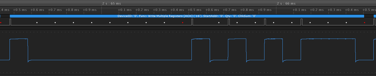
In short, the longer the length is set to, the more frequently it goes offline to the point of being constantly offline if I am trying to poll around 30 or more registers (I need to poll about 90 registers in total to get access to all registers that I need). I attempted to cut down how many registers I was accessing by creating multiple pollers that were only checking the bare minimum (4 registers per zone) to be functional but by the time I had 4 zones setup (4 x 4 registers being polled) there was a constant altering of which zone was appearing offline. At present I have it setup with only 2 zones polling the 4 registers but the log is full of CRC and EOF errors. This alternates between a few seconds apart to several minutes apart and I cannot work out why.
To rule out hardware faults I tested the USB adaptor connected to a Windows laptop running CAS MODBUS Scanner which was able to poll 100 registers within a second.

==> /var/log/openhab2/openhab.log <==

2019-07-16 14:24:05.038 [ERROR] [t.wimpi.modbus.io.ModbusRTUTransport] - Last request: 01 03 00 60 00 04 44 17

2019-07-16 14:24:05.042 [ERROR] [t.wimpi.modbus.io.ModbusRTUTransport] - failed to read: CRC Error in received frame: 0 bytes: 

2019-07-16 14:24:05.048 [ERROR] [pi.modbus.io.ModbusSerialTransaction] - execute try 1/1 error: I/O exception: IOException CRC Error in received frame: 0 bytes: . Request: net.wimpi.modbus.msg.ReadMultipleRegistersRequest@11532a0 (unit id 1 & transaction 44715). Serial parameters: SerialParameters@2c2f7d[portName=/dev/ttyUSB0,baudRate=19200,flowControlIn=none,flowControlOut=none,databits=8,stopbits=1,parity=none,encoding=rtu,echo=false,receiveTimeoutMillis=1500]

2019-07-16 14:24:05.053 [ERROR] [pi.modbus.io.ModbusSerialTransaction] - execute reached max tries 1, throwing last error: I/O exception: IOException CRC Error in received frame: 0 bytes: . Request: net.wimpi.modbus.msg.ReadMultipleRegistersRequest@11532a0 (unit id 1 & transaction 44715). Serial parameters: SerialParameters@2c2f7d[portName=/dev/ttyUSB0,baudRate=19200,flowControlIn=none,flowControlOut=none,databits=8,stopbits=1,parity=none,encoding=rtu,echo=false,receiveTimeoutMillis=1500]

2019-07-16 14:24:05.060 [WARN ] [rt.modbus.internal.ModbusManagerImpl] - Try 1 out of 3 failed when executing request (ModbusPollerThingHandlerImpl.ModbusPollerReadRequest@1003ba3[slaveId=1,functionCode=READ_MULTIPLE_REGISTERS,start=96,length=4,maxTries=3]). Will try again soon. Error was I/O error, so reseting the connection. Error details: net.wimpi.modbus.ModbusIOException I/O exception: IOException CRC Error in received frame: 0 bytes:  [operation ID c7cc1064-4ff4-471c-9249-260c37617374]

==> /var/log/openhab2/openhab.log <==

2019-07-16 14:32:02.520 [ERROR] [t.wimpi.modbus.io.ModbusRTUTransport] - Last request: 01 03 00 60 00 04 44 17

2019-07-16 14:32:02.523 [ERROR] [t.wimpi.modbus.io.ModbusRTUTransport] - failed to read: null

2019-07-16 14:32:02.526 [ERROR] [pi.modbus.io.ModbusSerialTransaction] - execute try 1/1 error: I/O exception: EOFException null. Request: net.wimpi.modbus.msg.ReadMultipleRegistersRequest@12c62c6 (unit id 1 & transaction 46488). Serial parameters: SerialParameters@2c2f7d[portName=/dev/ttyUSB0,baudRate=19200,flowControlIn=none,flowControlOut=none,databits=8,stopbits=1,parity=none,encoding=rtu,echo=false,receiveTimeoutMillis=1500]

2019-07-16 14:32:02.528 [ERROR] [pi.modbus.io.ModbusSerialTransaction] - execute reached max tries 1, throwing last error: I/O exception: EOFException null. Request: net.wimpi.modbus.msg.ReadMultipleRegistersRequest@12c62c6 (unit id 1 & transaction 46488). Serial parameters: SerialParameters@2c2f7d[portName=/dev/ttyUSB0,baudRate=19200,flowControlIn=none,flowControlOut=none,databits=8,stopbits=1,parity=none,encoding=rtu,echo=false,receiveTimeoutMillis=1500]

2019-07-16 14:32:02.531 [WARN ] [rt.modbus.internal.ModbusManagerImpl] - Try 1 out of 3 failed when executing request (ModbusPollerThingHandlerImpl.ModbusPollerReadRequest@1003ba3[slaveId=1,functionCode=READ_MULTIPLE_REGISTERS,start=96,length=4,maxTries=3]). Will try again soon. Error was I/O error, so reseting the connection. Error details: net.wimpi.modbus.ModbusIOException I/O exception: EOFException null [operation ID 4b957a3d-4d28-4e70-8e5f-94259bc392b9]

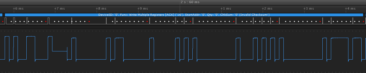
NOTE: I am aware the logs and the screenshot from CAS show different BAUD rates. I tried lower and higher to rule out that as a problem. Also CAS does not have a 0 offset so the value of 81 in OH appears as 82 and so on in the screenshot.


That really suggests corruption on your serial line.

That really really suggests corruption on your serial line.

This kind of thing can happen, but it can be a red herring. Cheap USB-RS485 adaptors often do not isolate the line completely from the host, you can get earth loops and so on causing noisy line. Obviously that effect varies between hosts.
Different hosts UART/software can be more or less effective at handling shaky serial data.

In the first case, take a hard look at your physical layer. RS485 requires termination resistors, either external or by selection in the device(s). Most RS485 adaptors provide bias, so you shouldn’t need to worry about that. Use twisted pair cabling (Cat5 is fine). Take care to avoid contact with power cabling, and if possible do not allow parallel runs with nearby power cabling.

If possible, I would be looking at more modest line speeds. In real life, 9600 is fast enough for almost anything.

I’ll give termination resistors a try (currently unused as the device installer manual did not specify them as a requirement so I thought it may have something built in) but I find it strange that it worked flawlessly when I tested it on another device. The host UART shouldn’t make any difference as that is only the short USB run, the converter is the one receiving the signal and that is the same on both devices. The cable in use is a pair from a CAT6 cable and aside from the travel down the wall it is not in contact or adjacent to any power runs. The run is also not very long, perhaps 10 meters in total so I would not have expected external noise to be an issue.
As for the rate, 9600 was the default and I was happy to leave it at that, I simply tried lower (to attempt to reduce the chance of noise impacting it) and higher in case it were some strange timing thing that OH or the Pi were doing.

10 metres at 9600 ‘should’ be bombproof.

Termination isn’t a requirement of any particular device, it’s a bus thing. Everyone’s job and noones’s job. Many devices are fitted with resistors, selected by a link, but I’ve rarely seen manuals mention them, let alone explain when needed.

You may have to meter the USB dongle to find out if it has a 120R or so across the A/B terminals. They often do but keep it a secret.

So I’ve terminated each end with a 200R resistor (which from I’ve read should be fine and are the closest to 120R that I have on hand) and set the baud back to 9600 but it’s still throwing the CRC errors repeatedly.
I should add that this is only a two wire connection as the HVAC controller uses 24VAC and has no ground reference or terminal to attach a 3rd wire to (most other RS485 devices I’ve worked with have the 3rd wire and omission can lead to signal noise). That being said I still don’t understand why the laptop had no issues reading from this device (Or maybe it did but suppresses any errors with retries).
Is there a chance it has to do with the implementation of the protocol in the binding?
Is there a way I can test it without using the binding?

As a side note, in this (http://www.ti.com/lit/an/slla070d/slla070d.pdf) TI datasheet it says regarding unterminated connections “should be used only in applications with data rates ≤200 kbps and short distances” of which 9600 is well below 200kbps and I’d argue that the ~10m I am running being less than 1% of the maximum RS485 distance would constitute a short distance.

Right you are @rossko57 , I just checked and the dongle does have a 120R built into it (with a really nice tolerance too, measuring at 120.2)

Humm, for just a 10m two-device line, a term at one end only would normally get away with it.
There’s something nasty at work here, but it is certainly worth trying a term at both ends, the proper way.

Confident in the Pi power supply?
Any other wired services connected to the Pi that may be giving an earth loop?

It’s the genuine Pi SMPS adaptor so I would like to think their suggestion is suitable. That is the only thing connected to the Pi other than the USB converter. There’s an onboard Razberry 2 and I am connected via Wi-Fi so no other potential sources.
I will get a matching 120R resistor for the remote end just to rule that out as I also measured the pins on the back of the control unit which has a toggle switch and the switch changes between 1.5K and 32K resistance. There is NOTHING in any of their documentation about the switch and having it in the option that measures 1.5K with the 200R in place gives less frequent errors than in the 32K position so I can only assume it is some kind of built in termination.
I will also try another power supply as my multimeter was measuring 49.98Hz with periodic spikes (presumably from the poller service) on the data line when the control unit was disconnected (50Hz is our power supply here) so I’m wondering if there is potential noise from the official supply. It may just happen to be that the stop bits are triggering a bad reading from the multimeter as it’s not a super expensive one.
Will report back later with results and if I fail to get the desired results I’ll grab out my logic analyser and do some deep diving.

This may be a biasing resistor network. Idling RS485 lines should not be allowed to float, but should be pulled to a “logic one” condition, so as to present a continuous serial stop bit. An active transmitter will overcome this.
It’s to prevent spurious data pickup. One of the line pair gets a resistor to 0v, the other to +V. Your meter will probably show 5V on DC range between A and B.
You can meter with openHAB stopped of course to rule out data packets.

In principle, only one device needs to apply biasing so I would think your USB dongle does that. In practice, individual devices often have onboard biasing as well.
Strong biasing by several devices limits the number of devices you can put on one bus, so they may well have provided switchable selection. (You’ll be fine with just two biasing devices)
It’s odd to do that and not provide a switchable terminator as well, but just about every Modbus device has some manufacturer quirkiness :wink:

In this case, the bias resistors could well be acting like a poor quality terminator, so yes do try a more standard one.

Just in case there are fighting biases, there is sometimes ambiguity about A/B or +/- terminals. Some devices will work better one way round (a few are truly reversible polarity). Worth a try reversing one set of wires, it will do no damage. Most likely won’t work at all. Maybe meter DC at both ends with bias on and wires disconnected to confirm polarity.

Hmm, it is normal enough to pick up a mains “hum” on any length of unshielded cable. But the idea of twisted pair is that both wires pick up the same hum, which cancels out when one wire is treated as + and one -. It should really be undetectable with your meter between A and B.
Just check you are using a proper pair from the Cat6 cable, not one wire from each.

I doubt that hum is leaking from your Pi power supply - that’ll be a high frequency switcher thing, not running at 50Hz.

However we might expect an earth loop to create hum. The DC supply at your HVAC may very well be linked to mains earth. If the DC supply at the Pi is linked to earth as well, we have a possible loop.
I would not expect a decent wall wart type SMPS to be linked to earth, but you could perhaps meter from its DC 0v to earth on its mains plug. And also mains neutral - some nasty chinese products do this and should be binned on discovery.

This is greatly encouraging that we are poking in the right area here :smiley:

So I bought a 120R terminating resistor today to rule out mismatched impedance and the result appears to be the same as without any terminating resistor :frowning:

My meter (with OH stopped) shows 0V between A and B. I tested between GND and 5V and A and B and it shows 5V between 5V and A, B or GND. I checked for resistance between each of these too and I get 61R between A and B (Owing to the two termination resistors) and 2.16K between GND and A OR B which seems to indicate that they are both being pulled to ground to stop the line floating. There are 3 resistors and diodes on the RS485 side of the circuit, the 120R and 2 x 4.7K resistors. I assume the diodes are lending to my reading of 2.16K as I would expect closer to 2.36K if it were 2 x pulldowns and the 60R between the terminals?

It’s definitely a pair from the cable, it looks like my meter is just very sensitive to the noise as having it disconnected and the cables near any sort of power line is enough to have it give the same reading so my guess is that’s what it was picking up and probably not an issue on the line. Connecting any probe of the meter to any terminal on the board (leaving the other floating) also netted the same result.

The HVAC supply is 24V AC, not DC. The power plug has no earth connector on it, neither does the one for the Raspberry Pi so I think an earth loop can be ruled out.

I don’t know what else to try :slightly_frowning_face: I was contemplating connecting my logic analyser to the dongle but my PC that can handle the data rate from it is too far away and I’m not sure my laptop could handle it (Saleae Logic 8)
I really want to get this working 100% though as the plan is to relocate the existing controller and replace it with a wall tablet with HabPanel.

I was wildly optimistic with my statement about expecting 5V, forgetting RS485 specs…
You should expect a standing DC bias voltage between A/B, but it’s more in the 200mV area. Could you check again? This part rarely messes up in reality.

Yes, there’ll likely be protection diodes between lines and power rails to prevent excessive swings and reverse polarity.

You mean the DC part is on the PCB … those chips are not running on AC!

Good news, these can be horrors to sort out.

This is rather a shot in the dark, but try this; use one of your unused Cat5 pairs (twist the wires together) to create an earth link between HVAC and Pi. You may have to improvise at the Pi end to link “earth” to Pi 0v rail.
I would not recommend this unless you are confident neither end has a real mains earth.

A better alternative here would be to spend a little more on a USB/RS485 adaptor that has genuine isolation between interfaces. They have a little onboard power supply and opto-couplers so that there is no electrical connection between USB and A/B at all, eliminating loop effects.

A similar but different trick to try is to connect all the unused Cat5 wires to earth/0V at one end only. A kind of rubbish screening. If this affects your error rate, consider using screened Cat5, STP.

I am convinced we are looking at a physically flaky/noisy serial connection from your description of CRCs and also being able to affect error rate.

BUT

We cannot entirely rule out some logic problem. Modbus being master-slave bus transaction based will generate CRC errors if someone speaks out of turn and tramples on the other’s messages.

I do not consider this will be an openHAB problem in general, or everyone else would suffer.
It’s conceivable that query-response can break down when the slave is very slow to respond, and master retries just as slave responds. If that were the case you would see timeouts in your openhab.log as well as CRCs, please look closely.

The operating system at the Pi should prevent any other user doing anything to the USB while openHAB has hold of it. Shouldn’t it?! I’ve never heard of such conflicts, but maybe something can bypass the permissions.

We’d better revieiw your modbus Bridge and Poller things definitions for anything odd.

An alternative source of trampling is the HVAC. Some are notorious for breaking Modbus “rules”, and acting like master as well as slave. Seems unlikely as it would not trample on its own messages to cause CRC errors detectable at openHAB, but rather trample OH transmissions, so “losing” requests and again resulting in timeout logs. Again we’d better know brand, model, and modbus adaptor model if add-on.

With the HVAC controller disconnected I am getting 0V on the line, with it connected I am getting around 30mV.

Yes it is running DC on the PCB, but I have nothing referenced to ground I can attach to before that.

I’ve got no problem doing that if I knew that were the cause, but without knowing for sure I’d hate to waste the time and money waiting for it to have the same results.

I did not think it would be an issue overall, rather a possible specific use case problem or bug.

I don’t see anything referencing a timeout, only EOF which occurs occasionally and is reproducible by disconnecting the controller from it’s wall plate.

I’ve posted screenshots of what I had setup for Bridge, Poller and Data things in my first post.

The controller is a Smart Temp Australia, Easy Zone Touch which is a parasitic zone controller to our Daikin reverse cycle ducted system. http://www.thermostat.com.au/Documents/Manuals/sz-ezt-InstallManual.pdf

I am wondering if it is an issue with the EZT as I was able to get it to produce errors connected to the Windows laptop by repeatedly polling the 100 registers. Here is an example of such a response from the CAS software:

[00:17:18] <= Response: 01 03 C8 00 06 00 BA 00 00 00 00 00 00 00 00 00 02 00 01 00 00 02 58 00 32 00 00 00 04 00 01 00 03 00 01 FF FF 01 0D 00 20 00 20 00 20 00 53 00 6D 00 61 00 72 00 74 00 20 00 54 00 65 00 6D 00 70 00 20 00 41 00 75 00 73 00 74 00 72 00 61 00 6C 00 69 00 61 00 20 00 20 00 20 00 20 00 20 00 20 00 20 00 20 00 45 00 61 00 7A 00 79 00 20 00 5A 00 6F 00 6E 00 65 00 20 00 54 00 6F 00 75 00 63 00 68 00 20 00 20 00 20 00 20 00 20 00 20 00 01 00 4D 00 61 00 73 00 74 00 65 00 72 00 20 00 20 00 20 00 20 00 01 00 F5 00 D7 00 E1 00 01 00 54 00 68 00 65 00 61 00 74 00 65 00 72 00 20 00 20 00 20 00 00 00 E6 00 DC 00 BE 4F 8A 
[00:17:18] => Poll: 01 03 00 00 00 64 44 21 
[00:17:18] <= Response: 01 03 C8 00 06 00 BA 00 00 00 00 00 00 00 00 00 02 00 01 00 00 02 58 00 32 00 00 00 04 00 01 00 03 00 01 FF FF 01 0D 00 20 00 20 00 20 00 53 00 6D 00 61 00 72 00 74 00 20 00 54 00 65 00 6D 00 70 00 20 00 41 00 75 00 73 00 74 00 72 00 61 00 6C 00 69 00 61 00 20 00 20 00 20 00 20 00 20 00 20 00 20 00 20 00 45 00 61 00 7A 00 79 00 20 00 5A 00 6F 00 6E 00 65 00 20 00 54 00 6F 00 75 00 63 00 68 00 20 00 20 00 20 00 20 00 20 00 20 00 01 00 4D 00 61 00 73 00 74 00 65 00 72 00 20 00 20 00 20 00 20 00 01 00 F5 00 D7 00 E1 00 01 00 54 00 68 00 65 00 61 00 74 00 65 00 72 00 20 00 20 00 20 00 00 00 E6 00 DC 00 BE 4F 8A 
[00:17:17] => Poll: 01 03 00 00 00 64 44 21 
[00:17:17] <= Response: 01 03 C8 00 06 00 BA 00 00 00 00 00 00 00 00 00 02 00 01 00 00 02 58 00 32 00 00 00 04 00 01 00 03 00 01 FF FF 01 0E 00 20 00 20 00 20 00 53 00 6D 00 61 00 72 00 74 00 20 00 54 00 65 00 6D 00 70 00 20 00 41 00 75 00 73 00 74 00 72 00 61 00 6C 00 69 00 61 00 20 00 20 00 20 00 20 00 20 00 20 00 20 00 20 00 45 00 61 00 7A 00 79 00 20 00 5A 00 6F 00 6E 00 65 00 20 00 54 00 6F 00 75 00 63 00 68 00 20 00 20 00 20 00 20 00 20 00 20 00 01 00 4D 00 61 00 73 00 74 00 65 00 72 00 20 00 20 00 20 00 20 00 01 00 F5 00 D7 00 E1 00 01 00 54 00 68 00 65 00 61 00 74 00 65 00 72 00 20 00 20 00 20 00 00 00 E6 00 DC 00 BE 57 D5 
[00:17:16] => Poll: 01 03 00 00 00 64 44 21 
[00:17:16] Error - Modbus message invalid length, short
[00:17:16] <= Response: 57 D5 
[00:17:16] => Poll: 01 03 00 00 00 64 44 21 
[00:17:15] <= Response: 01 03 C8 00 06 00 BA 00 00 00 00 00 00 00 00 00 02 00 01 00 00 02 58 00 32 00 00 00 04 00 01 00 03 00 01 FF FF 01 0E 00 20 00 20 00 20 00 53 00 6D 00 61 00 72 00 74 00 20 00 54 00 65 00 6D 00 70 00 20 00 41 00 75 00 73 00 74 00 72 00 61 00 6C 00 69 00 61 00 20 00 20 00 20 00 20 00 20 00 20 00 20 00 20 00 45 00 61 00 7A 00 79 00 20 00 5A 00 6F 00 6E 00 65 00 20 00 54 00 6F 00 75 00 63 00 68 00 20 00 20 00 20 00 20 00 20 00 20 00 01 00 4D 00 61 00 73 00 74 00 65 00 72 00 20 00 20 00 20 00 20 00 01 00 F5 00 D7 00 E1 00 01 00 54 00 68 00 65 00 61 00 74 00 65 00 72 00 20 00 20 00 20 00 00 00 E6 00 DC 00 BE 57 D5 
[00:17:15] => Poll: 01 03 00 00 00 64 44 21 
[00:17:15] <= Response: 01 03 C8 00 06 00 BA 00 00 00 00 00 00 00 00 00 02 00 01 00 00 02 58 00 32 00 00 00 04 00 01 00 03 00 01 FF FF 01 0E 00 20 00 20 00 20 00 53 00 6D 00 61 00 72 00 74 00 20 00 54 00 65 00 6D 00 70 00 20 00 41 00 75 00 73 00 74 00 72 00 61 00 6C 00 69 00 61 00 20 00 20 00 20 00 20 00 20 00 20 00 20 00 20 00 45 00 61 00 7A 00 79 00 20 00 5A 00 6F 00 6E 00 65 00 20 00 54 00 6F 00 75 00 63 00 68 00 20 00 20 00 20 00 20 00 20 00 20 00 01 00 4D 00 61 00 73 00 74 00 65 00 72 00 20 00 20 00 20 00 20 00 01 00 F5 00 D7 00 E1 00 01 00 54 00 68 00 65 00 61 00 74 00 65 00 72 00 20 00 20 00 20 00 00 00 E6 00 DC 00 BE 57 D5 
[00:17:14] => Poll: 01 03 00 00 00 64 44 21 
[00:17:14] <= Response: 01 03 C8 00 06 00 BA 00 00 00 00 00 00 00 00 00 02 00 01 00 00 02 58 00 32 00 00 00 04 00 01 00 03 00 01 FF FF 01 0E 00 20 00 20 00 20 00 53 00 6D 00 61 00 72 00 74 00 20 00 54 00 65 00 6D 00 70 00 20 00 41 00 75 00 73 00 74 00 72 00 61 00 6C 00 69 00 61 00 20 00 20 00 20 00 20 00 20 00 20 00 20 00 20 00 45 00 61 00 7A 00 79 00 20 00 5A 00 6F 00 6E 00 65 00 20 00 54 00 6F 00 75 00 63 00 68 00 20 00 20 00 20 00 20 00 20 00 20 00 01 00 4D 00 61 00 73 00 74 00 65 00 72 00 20 00 20 00 20 00 20 00 01 00 F5 00 D7 00 E1 00 01 00 54 00 68 00 65 00 61 00 74 00 65 00 72 00 20 00 20 00 20 00 00 00 E6 00 DC 00 BE 57 D5 

As you can see the poll is being sent correctly, ID 1, F03, 00 Start address for 100 registers but if you have a look at the line that failed, all that was returned in the response was the checksum. There was no other data in the response which makes me feel perhaps there is a chance it might be a slave issue.

That’s very disappointing. Maybe your USB/RS485 dongle does not have any bias after all. Still, as we said, you only need one to work this. What do you get at the HVAC A/B with power on but no connection? Maybe with and without the mystery switch thingy?

It may end up with the “best of a bad job” combination being only one terminator and the panel’s bias applied.

Most likely this is a one-way problem then. The HVAC is seeing all OH messages and responding (maybe badly) or we’d get many timeouts.
That doesn’t rule out signal weirdness of itself, since Tx/Rx at either end may be more or less picky.

Okay, have a better understanding. Was thinking of HVAC with sheet metal, big motors, etc. :wink:

I note there’s an option to link this panel to a “host” HVAC’s thermostat, which would possibly give an earth path. Is yours standalone?

ahhh, interesting. I wonder what happens if the panel turns round a query really quickly, not following the modbus rules about gaps between messages. The receiving UART/system buffer may sync up anywhere in the incoming message.
There’s not much we could do about that from OH end.

Looking at your Things, not much to say.
I would set your panel (and thing of course) to 9600, its default.
These errors are almost certainly recoverable, and like any well behaved Modbus master OH does do retries autonomously, 2 retries by default.

If that’s all that you see in logs, then try 2 has worked.
I’d like to see what happens when you get this “Thing going offline” event, it must be different.

We may have to get this working as well as possible, and then make it fault tolerant of what’s left.

Unfortunately I can’t get to that as the terminals are on the wall plate that the controller connects to once mounted. The measurements I took with both ends enabled were from the USB end.

Mine is standalone

Yes I noted that in most cases that it does recover after 1-2 failures, but I want to work out WHY it’s failing to prevent it occurring in the first place or getting worse over time. The current poller is only polling a very small number of total registers and these errors increase the more polling I am doing. When I had multiple pollers going was when I saw them going offline momentarily.

So I grabbed my Logic8 out and managed to get short bursts of capture on the laptop that I could analyse on my desktop. This first shot shows the digital signal at the top and the lower is the analog signal. This was taken measuring between A and B from the dongle whilst connected and polling (Although I’m not too sure why it says the function is 16 with 0 qty when the data in the logs indicates it is using function 03. Possibly a bug with the protocol analyser, I’ll raise this with Saleae)


You can see on the analog lines that the signal is fairly clean so I don’t think noise is a problem as it’s showing barely a ripple. The resolution of that graph is -1V > 1V
The above image is from a good reading.
This image is from a failed reading and it looks like there may be something causing a latchup to occur for 3 pulses. This is the only anomaly I could detect in that poll.

Things look slightly more interesting when I connect the probes up between A>GND and B>GND (Although knowing very little about analysing RS485 this could be well within spec) as you can see the data pulse appears normal with the opposing channel being in the opposite state as expected. What is interesting to me is what you can see after the A2 measurement marker where there appears to be a faint data pulse on the lines which also is a differential signal with nice clean edges but is in a time outside of when the poller was running. I am not sure if this is noise coming from the controller interface to relay card which also appears to be using some kind of RS485 or hacked apart MODBUS (Scanning slaves with CAS showed a slave 0 that wasn’t responding to commands in the correct fashion but was still reporting something back) but it appears approximately 8ms after every poller register poll.

A less detailed view but shows the continued pattern of faint signal after poller runs.

My first thought was signal reflection as I am now no longer measuring a differential signal, but if you look at the close up the signal patterns are different as well as the fact that there is a clear delay every time that wouldn’t be there if it were. The only other thought I had was that it is the slave responding and the dual pulldowns on the USB controller might have been too much bias for the HVAC controller to overcome and hence was manifesting as a very faint signal only visible in analog when measured to GND when most other datasheets show one line pulled up and the other down? The other solution is that I’ve measured it completely wrong as I normally only use it on TTL or I2C lines :laughing:
The USB>RS485 adaptor I’m using is a generic TE661 model that is cheap so I’m not against pulling off the SMD resistors if that might help but I don’t want to waste my time if I’m reading it wrong. If I were to replace the dongle with another I’d ideally keep it a similar form factor as it’s all internally mounted in an enclosure and the ‘industrial’ units I’ve seen are all quite large by comparison.

Okay, maybe measure DC volts between the wire pair at the far end with it disconnected there. I’m not happy there is a good bias yet, maybe the meter is a bit flaky - you could use your signal analyzer to separately find out what bias each end applies.

Ooh, pictures! Yummy! Nice to have the tools :smiley:

Screenshot 1 - lovely, nice clean corners and very little ringing. As it should be I expect, we’re looking at dongle generated signal right at the dongle, yes?
Not sure I’ve understood your scale - but its either 1V or 2V swing and that’s plenty solid for RS485. We only need 200mV difference A/B.


Screenshot 2 - woah, that “half step” during transmission in the trace is wrong wrong wrong. I’m guessing that represents the 0V level, i.e. A = B.
Hopefully this is a wonky connection to your analyzer, is that possible? I think you need to repeat this exercise with good solid electrical connections. It may be an artifact of some analyzer glitch - but if you’re confident it coincides with polling errors we should take it at face value. Maybe check recorded data for half-steps when you know it worked. These might appear in the master or slave traffic.

I’d be considering binning the dongle on this evidence. Not entirely impossible it’s a cable fault, a short circuit by pinching or penetration somewhere.


Screenshot 3 - my analysis. Not so bad, really.
We’re on a longer timescale here. The first nice big clean data package is the Modbus poll query from OH. Then an idle gap of some 8mS, and the next longer package is the response from the HVAC.
That’s allowed to be smaller and noisier as its coming from the far end of the cable. Again, I’m not sure of scale but we want 200mV differential, I think that looks like 500mV or so,
There is noise and jangle, but we are not looking at the important version here, the A/B difference, and I think most of that noise and drifting will disappear.

It’s more obvious here that bias between A/B during idle seems to be missing. Not yet convinced all is well in this area.
Both traces appear to idle at the same level. We want one high and one low, rather like the data traces mirror each other. Maybe your meter is telling the truth after all.

Really sure there are no links on the PCB inside the dongle to select bias?

The bias should be one pulldown and one pullup (they would both show resistance to ground when powered off via the rest of the circuitry)

Last thing you need here, I reckon.

Sorry I realised I cut off the left side showing the numbers, but the bottom of the graph is -1 and the top +1 so it’s showing a ~1.1V swing between -350mV and 750mV.

It’s definitely not a wonky connection (It is 0V) and it only appears once in the captures that had one failure during that time and it’s also the section the protocol analyser reports as a CRC error.
That being said, upon looking at the captures again this morning, the 0V level that appeared in the capture coincides with the the gap between the master and slave transmission (I followed the pattern of pulses either side of it and the match). I’m not sure what’s causing it to go to 0V instead of pulled low but my guess is that the either the RS485 or RS232 IC on the dongle is interpreting that slow ramp down to the beginning of the slave transmission as a data low pulse, thus adding an extra bit to the front of the transmission which obviously makes the CRC mismatch.

I don’t know it would be a cable fault as I’ve tried multiple pairs from the cable and it’s a short run that I’ve inspected for visible damage.

Yes that’s roughly 600mV differential

No bias selector, the jumpers are to “disconnect the RS485 circuitry to allow it to be used as a TTL from the pins”. The same idle level as well as the same resistance when I was checking A>GND and B>GND as well as getting no reading between the 5V and A/B is what makes me feel they are both pulling down instead of alternate.


Pretty sure the 3 R’s and I should think diodes at the terminal end are the bias and terminator set up.
+5V - Rbias - A - Rterm - B - Rbias - 0V and similar for the protection diodes.
Plug that dongle into any USB port and see >200mV DC across A and B, else it’s busted.

I follow what you’re saying - that the data before the half-step is master and after is slave, - but the duration of that 0V half-step is under 0.5mS.between end of master query and begin of slave response.

That’s bad. There is a spec for minimum gap between messages. It’s supposed to be a character and a half, 12 bit times at 9600 = 4mS. Now of course interpretations of spec can be pretty sloppy, but 0.5mS is chancing it.
The RS485 transmitters take a finite time to turn off, and more importantly simplistic designs control TX disable with a timer from end of data. They’re allowed to hang on (transmitting a long stop bit) after the end of the data.
Compare that with the 8mS gap in screenshot 3

The other bad is that we shouldn’t ever see 0V of course - either a TX somewhere is doing 0 or 1, or the bias should hold it to 1/Stop bit.
I have a feeling what we’re looking at with that particular half-step is both TX on at once.

Who to blame? Don’t know.
Note that if bias is missing, spurious data can be detected at odd times and elicit some response - that could be like setting a wheel in motion that pops up some time later, perhaps when the other end has decided to do its own thing. I wouldn’t rule out missing bias giving simultaneous TX once in while.

EDIT - as an aside I forgot earlier

There are no slave 0 in Modbus. But - master is allowed to broadcast to ID 0. In theory, slaves should not respond. In practice, many manufacturers provide some non-standard activity, for example it might prompt a message self identifying, or it might let you set slave ID remotely, etc.

Definitely 0V.
I’ve taken the dongle out so I can do some more measurements and I am 99% sure they have biased both to GND instead of one to VCC as there is no measurable resistance between the GND pin and one end of each of the two bias resistors (Marked in red) and there is no measurable resistance between the other sides of either resistor either (Marked yellow and blue for A/B test points).
With that in mind I am wondering if I desolder and rotate 90’ the resistor to the orange marker orientation, that would bias B to 5V VCC which should be correct to RS485 specs wouldn’t it?

I’ve just checked all the other non erroring polls and most of them have between 3.5 and 9ms delay between responses. Do you think it could be the incorrect bias I mentioned in the top of this reply that is causing both to transact at the same time or could it be sloppy programming on the slave?

Edit to add:
You can see here the delay between master and slave transactions on the left side, the next poll 500ms later on the right is the one with the half step and you can see that it has no delay (Well >.4ms anyhow)

Picture illustrates the problem nicely. Assuming the poll query packet is the same, or at least the same length, you can get a ruler on the picture and see that the response fired up too early. HVAC is behaving naughty.
That may be an inherent problem. But - between these transactions is that unbiased 0V that shouldn’t be there. Let’s assume for now there is only one problem, and that is root cause of HVAC misbehaviour.

Re resistors on dongle. I’m having some second thoughts about this. These are quite high value aren’t they? Genuine bias resistors would be under 1K.

I would check around it with power on though, the diodes may mislead a meter and there be low measurable resistance between + and 0V rails (big capacitor etc.)

To be fair here, a great many RS485 transceiver chips will work okay without bias. The problem is that we don’t know that both of these will. Applying weak bias will do no harm, and we know that something is wrong. The dongle appears to be designed to apply bias, but maybe those resistors are just to limit too much float (and so both go to 0V)

4.7K

With power on and nothing connected it measures 5V between GND/A/B and 5V and resistance between each of those shows 0.0

What do you think the cause is then? Bias still or the USB dongle or bad programming on the HVAC resulting in it not waiting it’s turn? Something else?

That is my thought but all diagrams I have seen when I look up datasheets or how to guides show 1 pulling low and 1 pulling high rather than both low. They appear to pull low but a bit slowly leading to the ramp seen when I measure against GND instead of differential. According to a calculator I looked at those bias resisters would ideally be 540R pulled high/low rather than both low.

And it’s incredibly simple for the most part from a wiring perspective, only requiring a transmit wire, a receive wire, and a signal common wire (YES—please use a signal common wire, grounded at one end only—thanks!)
...
...
The objective of biasing is to make sure that the RS-485 line remains in a known, non-fluctuating state when no devices are transmitting. Biasing the entire network requires a single pair of resistors: add a pull-up resistor to +5V attached to the +V signal line, and a pull-down resistor to ground attached to the -V signal line. RS-485 networks such as Profibus, Optomux, and DH-485 (see below) typically have biasing resistors at the primary node.

The above was taken from RS-485 - To Terminate, Bias, or Both? and I have never heard of terminating the common line at one end only?!? In the usual applications I use (TTL/I2C) they require a shared ground or they are prone to a lot of noise. Seeing as how the USB has a ground I can connect to I will try that but I am unsure how that could benefit it.
The same guide strongly suggests that bias or termination are the most likely faults to occur so I will try moving my resistor to VCC if a 1 sided ground does nothing although that is still 4.7K and not close to the recommended 540R but I have very little in chip resistors in my inventory to try anything else.