My Central Heating Solution using Thermal Actuators

And that is why it is good to rely on a 4 wire actuator. If the boiler runs hot water is a system where all the zone are closed (or the radiators valves off) it can damage the boiler depending on the age of the boiler and the settings. Modern condensing boilers have a setting for this. When I run my heating routine.
The room temperature sensor changes, then
If the temperature is below a certain threshold for that room and the time of day AND the windows are closed then I open the radiator valve.
Because I don’t have the 4 wires actuators, I cheat and call for heat on the boiler 2 minutes after I open one of these actuators. On the other hand. It stop the boiler as soon as I closed the actuator. The actuators take between 2 a 3 minutes to fully open/close.

But, yes, calling for heat on an “empty” system can be dangerous.

1 Like

Never ever heard of this… The boiler has a temperature threshold as well as an over-heating valve (security valve) if the pressure (due to the heating) is to big. I dont see how any damaging is possible, unless there are at least two faults.

How many rooms do you have?
If our system was suppose to run this way, the boiler would be started almost all the time, (depending on the season ofcouse). Second, our floor heating is build into the concrete of the floor. It takes quite alot of time to heat up the floor. If it was build on wood, it would take far less time to heat up… On the other hand, floor heating build into concrete will hold the heat much longer after the actuator has been closed.

This is a picture of our heating system (manifold) with all the actuators (sorry about the mess, the picture was taken while I rebuild the solution to be using IHC system):

It’s just bad practice to allow pumps to run into closed systems.

The “safety” values are there as a safety feature, not for daily use.

So, yes, using the microswitches on 2 port valves and Manifold actuators to “call for heat” is a professional norm.

The ONLY Errata to that statement is IF you have at least 1 loop or radiator that is LOCKED open, then and only then is it permissable to run the heat source / boiler / furnace into a system without caring how many zones are open.

With modern modulating heat sources, they will vary their energy usage to counter the return flow temperature.

Meaning.

If the return flow temperature is only slightly lower than the target flow temperature, only a small amount of energy will be used.

I have a commercial client who counts the amount of open valves, to determine how many heat sources are required to meet the demand.

(For example, he normally installs 4 boilers and rotates the usage)

That’s an over pressure valve. All boilers should have them. They fail sometimes but that’s not the issue, the issue here is the thermal loop. The boiler is going to pump hot water in the system and expect a temperature drop after going though the loop. If the radiators or zones in the loop are closed then the water will more or less go back to the boiler straightaway without the expected temperature drop. Modern boilers can cope with that provided they have been told what to expect. Older boiler may get confused by this and just turn off and require a reset.

7 rooms with radiators. The boiler only runs when one of the rooms is calling for heat.

1 Like

Just a note.

Velbus thermostats have 8 seperate output states that can be mapped to different output devices

One to many
Or
One to one

So it is totally possible to have a thermostat open a valve and call for heat / cooling / ventilation separately.

If…

An installation only has single contact thermostats, how would the call for heat be isolated from the seperate valve openings.

(That was a hypothetical question, I know the required schematic)

Here’s a thought that I’m going to play with, because I’ve been asked to create radiator control for a client that can’t run any cables.

What if these WiFi smart plugs were wired up to simple 2 wire 230vac Electrothermic Actuators?

(HS100 & WTA & Plugtop <£40)

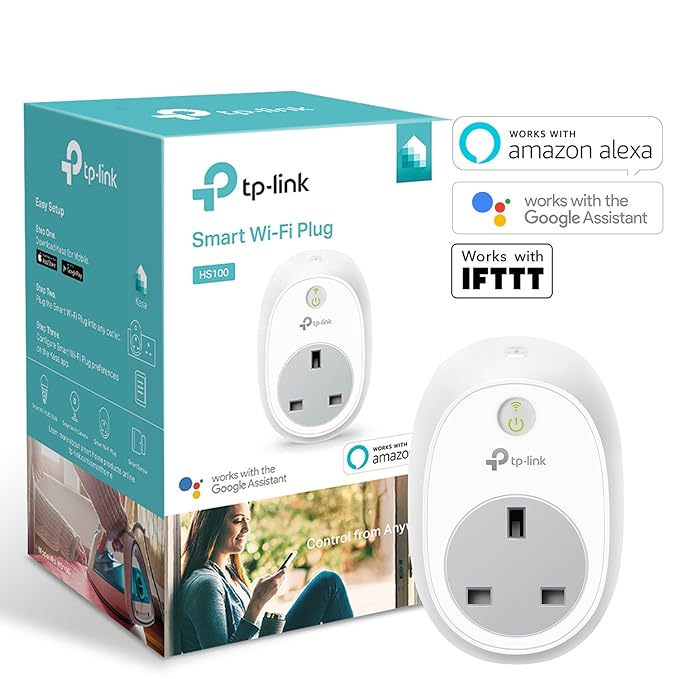
(Using the TP-Link OH Binding)

And have openHAB2 map a room thermostat to them and a heat call device?

(My client has Velbus glass panels {which have thermostats in} in each room, just not any way to control the flow to the radiator)

UPDATE April 17th

I’m happy to report that these TP_Link HS100 smart plugs work perfectly (and directly) with OH2, so with a NodeRed Flow, I’ve mapped the Thermostat Heater channel state of a Velbus module.
(I could just of easily mapped this in DSL Rules, I just happen to be learning NodeRed right now)

Thanks to @Confused for putting this concept out there in the first place.
I’ve been going down all kinds of dead ends looking for an effective solution.

This does seem like exactly how I implemented my setup originally. Nothing was hardwired, it was able to be returned to standard in seconds. I’ve since now decided to do a permanent installation as I’ve got a new house and the ability to do what I want :wink:

1 Like

It’s due to you posting this in the first place that put the idea in my head to start with.

I’ve just been looking for a 'ready made" solution that would look okay if I installed it for someone.

I really liked what you’d created :slight_smile:

1 Like

This is what our boiler is doing from it´s temperature treshold. Since the manifold is a very short but closed to the boiler, the temperature loss is close to zero, when no actuatores are open.

Do you have two boilers, one for heating and one for warm tap water? I only got one, so unless either a room or someone using hot tap water, our boiler will be on standby.

No, just the one. A combi boiler. Whenever a hot water tap is opened, the boiler will switch to hot water and go back to heating when closed. I have the heating schedules in the mornings set for heating before the bathroom is used. During the rest of the day, hot water doesn’t influence the central heating much at all.

Not all boilers can cope with that set up. Most modern ones can and even then most need to be told to expect it.

Same as ours then.
I still dont see the need to switch in the actuators.

It’s not a major issue.

If…

Your particular setup has a blender between the boiler and the UFH manifold, which is there to return the (~60°C) flow back to the boiler if the UFH return flow is up to target (never more than 40°C).

Then in theory it’s not a big deal to have the boiler on and not signal any heat demand.

However, if your system doesn’t have a blender, (which if you’ve only got UFH) and your boiler is set to limit the flow to 40°C, then it would be ‘nice’ for your boiler to know that none of the zones are calling for heat.
However, this assumes that you have a locked open loop / bypass so that the water can return.

The actuators in the WTA really come into play when there are multiple manifolds, with multiple UFH manifold pumps and 2 port isolation valves.

If you consider how this wet schematic might be wired to maximize water flow, so that it is routed where it is needed.

The picture is exactly how our heating system is made. Only changes are.
The Hot Water Tank, the Pump Pack and the valves are all build inside the boiler. And then our system is having 13 zones and no Raditors, it´s all floorheating.
Our boiler covers both hot tap water and floor heating, so it´s split up into two different sections each having an independ thermostat. But I guess thats quite normal, and your picture is just a principal drawing.

This is why I failed to understand the need for the actuator switch. The switch wouldnt make any change, as the room thermostats is controling the acutators for each zone/room.

So the picture doesn’t represent your installation then :wink:

I was only trying to get across how the actuators in WTA would make a difference in a system, that WASN’T like how yours is installed. :slight_smile:

The basic principle is…

Room thermostat triggers a 2 port valve / WTA

Microswitches in 2 port valves / WTA call for heat from the heat source, WHEN (and only when) the valve is fully open.

(Obviously this is only a simplified explanation, I’m happy to provide a schematic if you’re interested, but as you understand your own setup, do you want to know???)

1 Like

As a principal matter, it does :slight_smile:

Not really… Just trying to understand the need of the switch… Perhaps it was something I didn´t know and missed :wink:

1 Like

To be honest I always expected the return pipe would show a differential to the in pipe and was hoping to use this differential to work out if the heating was actually working hard or not. So if there was a large differential then the heating is working hard, putting a load of heat into the house and when it was a small differential the heating was fully up to temp.

However, hard data on my system said otherwise. I realise this is just my heating and systems may vary depending on flow rate and how good the radiators are, how many there are etc. But the graph below of heating in/out pipe was NOT what I expected.

https://imgur.com/71sbYNI

You can see there is seldom more than a 2*C differential and the out pipe comes up to temp and cools almost exactly tracking the in pipe. I think this just because the loop flow rate is high.

That’s a pretty efficient system you’ve got there then.

I monitor the gas consumption into the boiler, which gives me a pretty good idea of how are the system is working.

I think it’s the opposite, it’s more or less the original 1970s heating that might have had the burner replaced once, but the heat exchanger is still the rusty old cast iron thing in the garage and several of the radiators are so full of gunk they don’t heat at all :slight_smile:

It’s being upgraded to a condensing gas boiler in the old “hot press” with a few radiators being replaced in the next couple of months, will be interesting to see how this graph changes when i connect it up once the plumbers and spark leave :wink: