I am looking for a type of sensor that just reports weather a circuit is open or closed. I want to use this to integrate with an old-fashiond, “manual” thermostat. Changing the thermostat itself is not in the question.
So I need a sensor that signals “ON” when the thermostat closes (resistance ~0 Ohm) and “OFF” when the thermostat is opening (high resistance). Zigbee or Z-wave, whatever. But I haven’t been able to find any…
Does anybody know if such an animal exists?
What are the voltages involved? That’s probably going to dictate what options you have.
In general a simple relay should work though. But unlike the usual configuration you’d use the thermostat wires to control the relay, not to be controlled by the relay. On the other side of the relay you have something that reports when the relay is closed or open which, to that sensor, would appear like a button press.
On the DIY front, an ESP8266 or ESP32 running one of the ESP firmwares (ESP Home, Tasmota, ESP Easy, etc.) would be more than sufficient.
There are some Z-Wave relays that have a dry contact input that I think you can use to detect closed/open. I have not tried this, but it appears it would work:
Some of the old Z-wave window/door sensors have a dry contact input, but I don’t see those for sale now.

normally on old fashioned HVAC control circuits it is 24VAC low voltage control if the wires going to the thermostat are small 18 gauge (look like telephone wire) also the number of wires connected to your thermostat will be an indicator as well if it is 2 pretty easy and the thermostat likely has a mercury switch(glass bulb and mercury inside (which by the way it was so important with them to be mounted perfectly level) is mounted on bimetal and when it expands or contracts it opens and closes the 24 VAC to complete the circuit of a contactor coil that then while drawing current creates a magnetic field that engages the contactor relay contacts so putting dry contacts in the path may not accomplish what you want alone . However, you could add an additional 24 vac relay coil in series with your thermostat wire to also engage when thermostat closes it will then also close that relays dry contacts that you could use a device like was mentioned to see a change in the circuits state.
However if they are stranded heavier gauge and use wire nuts then you have a high voltage control and it is different and much more care should be used with fiddling with the thermostat.(but it will be possible to use a different solution more like a light switch control.
Other options would be things like opto-isolators determining when the current is flowing the opto-isolator led section which will forward bias a built into the opto isolator mosfet or Darlington pair switch circuit and that would control the dry contacts on the above mentioned z-wave device. or any other basic switch like device that you use to control light ckts such as the sonnoff zbmini
I have my thermostats connected to Shelly relays (Shelly 1 & 2.5). The thermostats are pretty standard 240V wall mounted room thermostats (see photo). You can use the output of the Shelly device to follow the thermostat or decouple it to be able to control the output with some more advanced logic from openHAB.

What ever approach you do decide make sure it is easy enough to bypass so if or when your a/c service tech has to do work he does not get confused or annoyed and charges you extra $$$ for trying to figure out (troubleshoot) how “your automation integration” works.
You can get some inspiration from my home alarm setup, where i use a 4 pole relay to detect if a 12 DC is active on a fibaro zwave smart implant. You could use any other technology of course, but it’s handy to use relays in these situations to transform higher voltage to just a binary signal.
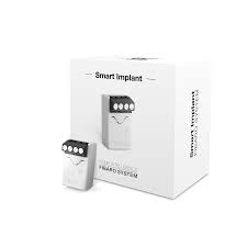
@Seaside Thanks for leading me towards the Fibaro Smart Implant!
So, if I understand the doc for the Smart Implant correctly, I can simply connect the thermostat (which is passive, probably bi-metal type) to one of the binary inputs to integrate it via Z-Wave. Seems to be just what I am looking for. Am I right?
It seems to be two versions of the implant - one is smiling, the other looks rather grumpy (see pictures). They both seem to have the model number FGBS 222. Do you know if they are really identical except from the direction of the “smile” (the include/reset button)?

No very likely not if you do you will damage the fibaro
How are you determining that your thermostat is passive?
Start by using a volt meter and with your HVAC operational meaning power is applied toHVAC and if you set the thermostat to ON (closed) the unit runs next set the thermostat to a setting that would be Off(open) Then using the volt meter either in AC or DC which ever gives a valid reading not ohms not amps but volts measure the voltage across the thermostat connections you previously had stated was open and closed
Note the value as well as if it is AC or DC that is also important to determine best solution for you. So you know what operating voltage the relay coil needs to be rated for.
Once you have determined the actual voltage that your thermostat is switching on and off you can take next step which is adding a appropriate type of relays coil connections in series with your thermostat so you can use the additional added relays “dry contacts” to become the binary input for your z-wave device.
Reading @Seaside tutorial it also references using a relay below is a direct quote from his article
The Fibaro smart implant can read up to two binary inputs. The Home Alarm is outputting 12V DC when for instance the alarm is triggered on the siren. Therefor I would fry the Smart Implant if I would put 12V DC on it. *In order to cope with that I attached a 4 pole relay. When the relay receives 12VDC it will shut the circuit (Normally Open NO) and you can get a binary signal out from that.
A thermostat is a switch that completes a circuit. the only way to see when a switch is closed is to put some kind of device that uses the same circuit when the switch is closed (ie this example a relay coil that reacts to the switch(Thermostat) being closed energizes the relay closing its dry contacts. This same as when you close a light switch it completes the circuit to allow the light bulb to draw current through the filament and glow. Your end result is you are adding a addtional relay in series with the other devices your thermostat is turning on and off and reading that added relay device (dry contacts state)
This is exactly the same approach as I described to get your current drawing voltage converted to a binary on off that a zwave device can read.
The appliance in question is a water heater. It is not electric - it is “fueled” by hot water from my central heater. Today, the thermostat closes/opens a ~19V DC circuit, fed from the central heater. It “clicks” even when the feeding circuit is deconnected. So I am quite sure the thermostat is passive.
Further, the thermostat earlier was connected in parallell with another passive thermostat (a room thermostat). This has already been replaced by a Zigbee relay closing/opening the 19V circuit, controlled by several Zigbee room thermostats (I have radiators in all rooms, so one “central” room thermostat was not satisfactory). The water heater is the last piece in the puzzle.
So, I still think: If I deconnect the 19V from the water heater thermostat, and instead feed the thermostat to the binary input of the Fibaro, this will work. I already have the relay in place to handle the 19V and there will be no electrical potential present to fry the Fibaro.
Ok That makes more sense. Yes if the thermostat (switch contacts) are no longer managing the 19 vdc the you can use them as the binary for any of the zwave or zigbee items the Sonoff zigbee ZBmini would also work perfect for this approach as well the s1 and s2 on it are isolated and if you hooked the thermostat contacts to its S1 and S2 switch terminals (they are isolated unlike some other ones) you would just need a power source to actually power the ZB mini and it would see your on and off with the added benefit of also acting as another router in your zigbee mesh network.
One point of caution: Zigbee and Z-Wave are very good, but every once in a while the system may miss a report. If your system relies only on those transition reports, it could do something unintended. You might want to think about how to handle the case of a missed on/off report. A secondary temperature monitor, a timer, etc., or increased polling?
Just one other question are you absolutely certain that the thermostat at the hot water heater was wired in Parallel with the room Thermostat and not wired in series?
If so then unhooking that thermostat and leaving the wires apart all should work fine. But if you have to short those 2 wires together to make hot water as well as having the relay closed it is not a parallel configuration.
Also I agree with @jswim788 he has also raised a very valid concern.
Actually, it did remind me of an alternate reason why a second thermostat may be used at the water
heater.
I am just wondering if possibly the thermostat at the water heater is being used as a high temp (at temp) cut out safety device.(would likely be the case if it was wired in series or it was do both safety cut out and also preheat for demand using both the NO and NC connections would be used but that would of course have a 3 wires/connections.
If it is pure parallel and system does work fine without that thermostat managing the 19 volt line then it likely is just used as way to insure you have preheated water ready for on demand as its only purpose.
Definitely worth the extra investigative work double checking to insure you are not bypassing some safety function and consider redundant or additional monitoring or at least adding some kind of solution that will cut off things in the case of a unexpected condition.
Yes - it works like this: If any one or both thermostats are “on”, the central heater starts. If both thermostats are off, the heater stops. They are both two-wire thermostats. The boiler has several security systems (pressure, temperature, mechanical failure/corrosion) independent of the thermostat. (And also, as it is heated by the radiator water, overheating is not likely to happen)
So any time some one wants hot water to say wash dishes or take a shower the entire house also heats up?
It would seem based on what you described if this is in fact 1 common 19vdc control ckt that is what would happen.
If that is the way it works I got to change my entire house because my wife is always complaining she is cold.
So I could say ok dear go wash dishes or clothes and you will warm up ! ![]()
Yes, that is how it was. There were manual valves on the radiators, so in a way it was possible to regulate them individually (however it was a lot of work). Now every radiator has its ovn thermostat and remote controlled actuators.
The idea is free ![]()