Thant is actually fair ![]()
order in progress ![]()
and while I am waiting for the stuff to be delivered I am doing researches…
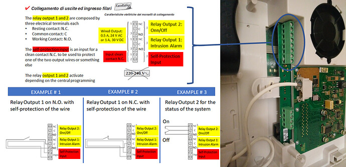
I have found few wiring diagrams on how to use the I/O in my central alarm system… anyone would be able to suggest how to use them for my oH project?
The only example that make sense to me is EXAMPLE # 3, in order to “read” the system and detect if ti is ON or OFF… in this case I would connect somehow Output Reley 2 to the NodeMCU and the system woudl know the status of the alarm…
Anyone can help me understand what are the EXAMPLE #1 and #2 for?
Thank you so much to everyone ![]()
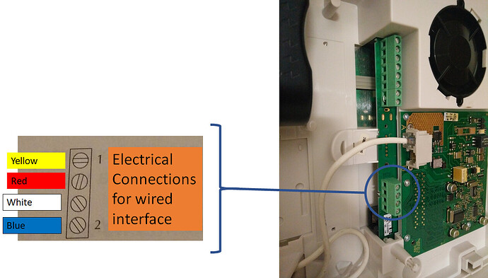
Doing more research… I have found an additional wiring map (not very useful, but I want to post it here)…
The problem is that the alarm system does not have anymore any support, therefore is impossible (for me) , to get any documentation…
I like this idea… how can I start? can I hook-up an adruino-like device and see what happen?? (not trying to make it simple.. just trying to understand from a newbie point of view ![]()
alternative, can I capture the “remote” signal and duplicate it? I would just need to turn the alarm on/off…
Thanks all ![]()
The idea was to find something that talked to the S310 e.g. a PC application provided by the manufacturer, that would use the PC’s COM port. Then you could eavesdrop on the conversation (by running a serial data monitor on the comms line), and so work out how to have your own OpenHAB setup communicate with it instead.
Alarm system makers generally jealously guard access to applications like that, and try to limit availability to genuine installers. Looking for such an application for an obsolete system may or may not improve your chances of finding it.
That assumes the manufacturer has used a more or less standard serial interface, and this “wired interface” is intended for that purpose.
It might instead be intended for a remote keypad and/or an expansion module for (say) extra wired zones. Again if you had some working example to eavesdrop on, it may be possible to work out the data exchange protocols so that it can be emulated.
If you cannot get hold of something (application, remote keypad) that is already set up to communicate with the S310 - your chances of hacking it are practically nil. It’s a security system, it’s not supposed to be easy ![]()
My first step woul be to find out just what this wired interface is for - a diagnostic/configuring port for an installers PC, a remote keypad, an expansion module? Is it an RS232 serial port, an RS485 port, or something completely non-standard?
Perhaps there are examples in the documents you have, or perhaps it suggests accessory modules you could look for further info about.
Alarm Terminology: The “self protection” they talk about is tamper protection, against the burglar simply cutting a wire to thwart the alarm.
In your case you can just link terminals one and two so that the S310 thinks all is well, this is the anti-tamper input. In the photo, a link is shown already in place.
Wiring to relay terminals 2 & 3 will give you an OPEN/CLOSED signal you can use with a digital input to OpenHAB. From Relay 1 , you can get an “alarm enabled” signal. From Relay 2, you can get an “alarm ringing” signal.
The examples #1 and #2 are supposed to help you use the relay to wire to an external bellbox, with tamper protection, the usual use for these facilities.
This is so clear now! thanks heaps! I get what I need to do now! At least in theory… getting the nodemcu delivered today… therefore I am going to have fun ![]()
anyone has any suggestion on which GPIO to use?
Many thanks!
no, unfortunately I do not have any PC application… I have sent a request to Hager, which I do not know if they would have an answer… I will update on this…
from my research it seems that the connectors are for an external wired keypad… somethign like thins: https://www.hager-sicurezza.it/sicurezza/allarmi-senza-fili/logisty-dual.mix/comandi/s630-22i/3757.htm
but I am still trying to get more info from the support team…
not sure, researching and will update here…
in summary I am tryign to get some info from the producer/support team… lets see what I can do… ![]()
Thanks a lot!
I got delivered my nodeMCU and I am trying to flash the Firmware… I have found tons of different way, but none is clear to me…
-
Sonoff-Tasmota GitHub refer to a “strange way to put the ESP” in Flash mode… my card has a “flash” button… don’t I just need to push that button???
-
I have also found anodeMCu flasher app…
The problem is that I am not sure how to trust “randomly downloaded SW”…
is there any "official way to flash the nodeMCU?
and once I have flashed the card with Tasmota, which IDE will I sue? is there any sample for a simple application?
Thanks all!
No.
The whole point of Tasmota and ESP Easy and the like is you don’t have to write any code. Everything is configured through a web interface. If you want to write code yourself, then you can use the Arduino IDE and you don’t need to flash anything on the NodeMCU. Your developed code IS the firmware for microcontroller.
Thank you @rlkoshak . Which way would you recommend to flash the nodeMCU?
I like this idea… anyone has any youtube video of the "final Result? ( have googled but not much…)
Although you did not ask me I tell you how I did flash my nodemcu to ESPEasy:
https://github.com/nodemcu/nodemcu-flasher
It looks like it is not developed any further, so you may need to find another flash software. You can even flash new firmware with the Arduino IDE.
But keep in mind because the ESP8266 is so widely used you will find thousands of ways to flash it.
Just pick one and try, if you are not satisfied pick another one and try again.
Which one? Tasmota, ESPEasy or Arduino IDE? It really depends on which sensors you want to connect to your nodemcu. You can find all that on the web pages of the respective firmware versions:
https://github.com/arendst/Sonoff-Tasmota/wiki
https://www.letscontrolit.com/wiki/index.php/Devices
Also, please keep in mind, you are not anymore in a “plug and play” world, you are now in a world where you need to tinker, flash, test, reflash and that maybe serveral times until it works like intended.
Thanks for the advice, I am just “scared” to download something on my PC which is more of a virus than a “firmare flashare” ![]()
I have seen few options online with Arduino IDE which I think they will work well ![]() I will report back here my experience form an absolutely newbie…
I will report back here my experience form an absolutely newbie…
I like the idea of Tasmota/ESPEasy, because it should be “less code development”… but again, as you said, it might not work for my case…
once flashed the nodeMCU (planning to do it with ESPEasy), I would have to “set what I want/need” to happen…
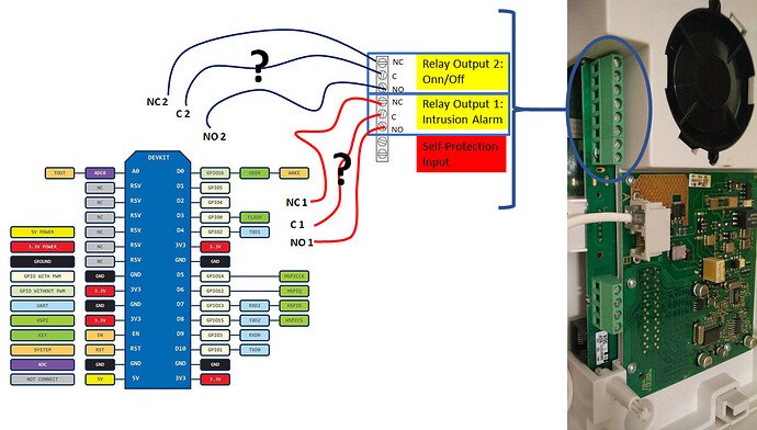
Lets say that now I have understood how the relay connectors in my alarm system work (alarm system status (on/off) and intrusion detection), how would you connect to the GPIOs?
I have ignore the “self protection” for now because I will not use it (for now)…
any ideas? Thanks heaps
Connect both the relay ‘Common’ terminals C1 & C2 to your nodeMCU GND, so that …well, there is a common connection.
Connect each of the switching contacts, say NO1 and NO2 to spare digital inputs, say D1 and D2.
I know nothing of nodeMCU, but if it allows you, you’ll need to configure “pull up” resistors on D1 and D2. That means that the inputs will be pulled to a HIGH state when nothing is connected (or the relay contacts are OPEN).
If it doesn’t have built-in pull ups, you will need to add some external resistors to do the job.
When the relay contacts CLOSE the input pins will go to state LOW, and you do whatever you do to get nodeMCU to report the change to OpenHAB.
I am embarrassed ![]() but how do I check for pull-ups? actually what does it mean? sorry
but how do I check for pull-ups? actually what does it mean? sorry ![]()
If your plan is to use ESPEasy, just go to the ESPEasy page.
https://www.letscontrolit.com/wiki/index.php/Relais
You are able to use a search engine???
You’re going to have to do some work here
Thanks! you guys are so patience ![]()
will do all my reading ![]()
Thanks for now!
To speed that up: you don’t need any pullups on the nodemcu, the pins have internal pullups.
To connect any dry contact switch just put the switch between a pin and gnd. For testing one of your DuPont cables should do it.
For other inputs: be aware that the max input voltage to the pins is 3.3 Volts. Some of them work with 5 Volts but you may fry them.
Updates on my project:
- Rasberry Pi3B+ arrived
- MicroSD 32 GB Delivered but faulty… returned and now awaiting for a new one

- Cables, Breadboard, NodeMCU and few diodes arrived
- nodeMCU in process to be flashed (via Arduino IDE) with ESPEasy.. I will report once done

I will be on holiday so I will not be able to do any development/test for the next two weeks, but I will use my time (if wife can handle this) to read more about this amazing world!
Thanks for the heads up… I am sure I would have fried the first attempt! ![]()
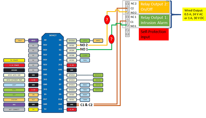
The picture below try to summarize what I should “physically connect” Thanks @rossko57
this make actually sense… the Alarm system will send a signal via NO2, if the alarm is armed, and via NO1, if there is an intrusion detected…
going back to @sihui point, from the specification of my alarm system, Relay 1 and 2 have an output of 0.5A, 24V (AC) or 1A, 30V (DC)
In my draft I have put two oval question marks, because would probably need a resistor (?) to ensure that the input to the nodeMCU is set to 3.3V…
Questions:
- why the relay outputs could be in AC or DC?
- what resistor (or anything else) should I use to avoid frying the nodeMCU?
thanks again
The relay contacts don’t output anything, They are just a switch, like touching two bits of wire together.
As they are a switch, there are limits on the amount of power they can handle. Those limits are described. They can switch AC or DC power.
That’s all pretty irrelevant here where they will only be switching microwatts to make a nodeMCU pin high or low.
