In part thanks to the help I got on this forum, I successfully completed my first DIY home smart device project - smart light switch. The total costs are 7$ (ESP8266 controller, solid state relay, and a few other components). It is integrated into the home automation system via MQTT and OpenHab2. It uses WiFi and NTP to detect the time and day, and sunrise/sunset calculator to figure out when to turn the light on and off. It also can be used in the old fashioned way (from the physical switch), and can be manually turned on/off online. It monitors and reports the temperature of the SSR, and has dual thermal runaway protection features. The code is posted on github.
Hey, that looks like a great work, congrats on your first DIY project! The documentation is also nice!
Out of interest, would you care to describe your motivation for the smart light switch to calculate switching times itself? That sounds like a great feature and justifies “smart”, however isn’t it redundant in combination with openHAB which already provides this logic and more?
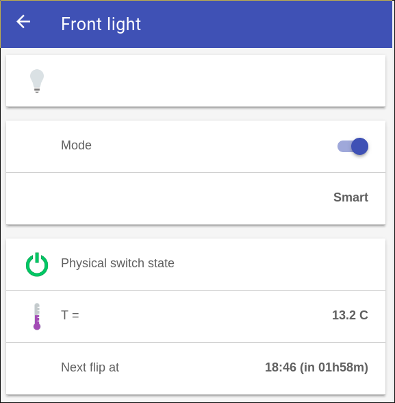
I tried to design my switch as robust and self-reliant as possible, both in terms of its operation, and in terms of safety (fireproof). For the former, the switch needs the WiFi/Internet connection only once, and very briefly (probably for 5 seconds or less) - to get the current time and date from the internet. After that it works as a smart (sunset/sunrise) switch by default, regardless whether it is connected to WiFi, MQTT, Internet, and/or OpenHab. This is great when you leave it running when you are traveling - even if your router dies, or you loose internet connection, the switch will operate correctly. It will also constantly try to reconnect to WiFi/MQTT/NTP asynchronously (in a non-blocking way), so once the services are back it will be back online. If it looses power, it goes to the default (smart) mode when the power is back. Then it will keep trying to connect to the Internet until it succeeds, and then switches to the smart mode.
So its main functionality (dark time lights on) works properly regardless of the WiFi/MQTT/OpenHab availability. The OpenHab functionality is just for convenience - to check the status, temperature, perhaps switch to the manual mode for a while. But the MQTT/OpenHab are totally non-essential for its correct operation - only the WiFi/Internet, and only briefly, is all it needs. Imagine my Windows PC (where the MQTT and OpenHab servers are running) malfunctions or freezes. The switch will operate correctly regardless, even if it is power cycled - as long as it can connect to the Internet briefly after each power cycle. And if it can’t, it goes into a safe mode (lights off), so no danger that it will do strange things (e.g. turning the lights on during the daytime).
Totally makes sense
I’ve studied the project page some more. The circuit is quite nice, I also like “built-in protection against abuse [and hackers]” - many interesting little details!
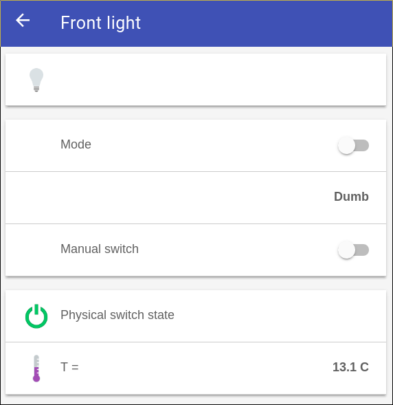
Thanks! I will be working to expand the functionality of the switch - I want to have a compile option which would compile it either as an outdoor switch (as it is now), or as an indoor switch. For the latter, the default (and safe) modes will be “dumb switch, lights off”, and it will turn off during the night in the smart mode (it will be on during the evenings, and in the mornings - only when its dark outside; with some randomness added).
do you have any pictures of this deployed in a box you could share? I’m interested in how much space it takes up and how you protected the high voltage and low voltage lines from eachother.
Sorry, no picture yet. I am waiting for some parts from ebay, and when I smartify my second exterior light switch I will do a better job - and then I’ll make pictures and post them. My first switch is safe and reliable, but a bit awkward to install. For the second switch I will likely place both SSR and the PSU in a single 3d-printed enclosure (tall and narrow), add a small (0.1A) AC fuse to the PSU, print a plastic cover for the ESP board (so it’ll become a very thin enclosure), and add this 6-way connector, so the ESP board will become detachable: 5pcs Micro JST 2.0 PH 6-Pin Connector Plug with Wires Cables 300MM Male & Female | eBay . Finally, I’ll use one of these thermal fuses: http://www.ebay.ca/itm/182390852074 .
I have already changed my code to handle other situations (for interior lights) - with or without the physical switch, and now one can also specify times to turn the light off during the night (slightly randomized) - so it will turn on when it gets dark, turn off for the night, and then turn on again in the morning until it’s bright. One can stage the times for 2 or more internal lights so the patterns will look totally natural (when you are away). I’ll poste the new code to github once I did some real life testing.
Very nice – i’ll be interested in your work. Have you thought about dimmable relays as well? And multiple? I have several switches with 3 relays inside my box..
One more question – what did you use for the front plate switch? In my ESP wall switch, I used just a standard AC switch.. but I found it took a lot of space up inside my box. Know of anything with multiple buttons or switches and a thin profile?
Here is the photo of the three components of my (v1.0) smart switch design:
It was designed to be usable with the existing light switch. In my case, I had a triple-switch box, and I smartified just one of them. The components were designed to fit into the spaces between the existing switches. I kept the original front plate. The design was to make the switch conversion discrete - from the appearance it looks exactly as before.