I have some Z-Wave devices connected via an Aeotec Z-Stick Gen5, but my thermostat of choice only connects with Zigbee. Since it took quite a bit of research to get to a functional setup, I thought about writing a guide here that could help other people to start from scratch and successfully connect to your Zigbee devices.
This is the hardware I had to purchase:
- Zigbee USB dongle - model E18-2G4U04B manufactured by Ebyte
- Device to flash the firmware - CC Debugger from Texas Instruments
- Jump wires - to connect the CC Debugger to the USB dongle
- Zigbee end device - in my case, Stelpro Maestro Smart Thermostat ASMT402AD
I bought the Zigbee stick and the CC Debugger from AliExpress - it took about 4 weeks to receive them, but they were inexpensive. I bought the wires from Amazon (you can look for “DuPont wires” there); they normally come in packs of 40 to 360, but here you only need 5 wires.
Choosing the Zigbee controller
Your main choice is to which which device to use as a Zigbee controller. If you use a ConBee or RaspBee controller, you need to use the deCONZ Binding. This binding does not communicate with the controller itself, but with the deCONZ software that should be running on your Raspberry Pi. Since I wanted to avoid an extra layer of software, I checked the controllers supported by the ZigBee binding:
The Nortek Security & Control HUSBZB-1 may be a good option if you are in North America and wants to connect both to Z-Wave and Zigbee devices. However, it is not compatible with the Z-Wave frequency used in Europe and it doesn’t make sense if you already have a Z-Wave stick. The Digi XStick looks interesting, but it was very expensive, so I went with CC2531, a Zigbee chip manufactured by Texas Instruments. This chip is integrated into a variety of USB sticks. The E18-2G4U04B mentioned above is inexpensive, readily available and comes with a nice plastic case (there are cheaper CC2531 dongles, but they may not have a proper case).
Obtaining the firmware and supporting software
The CC2531 chip does not come with the Zigbee firmware installed, so you have to download it from Texas Instruments’ website and flash it into your CC2531 USB stick. After creating an account on TI’s website, you can download Z-STACK-HOME (version 1.2.2a from 16-OCT-2015) from the Z-STACK-ARCHIVE page. You will need to confirm you won’t use the firmware for military usage and that you are not in a country with US software export restrictions (Cuba, North Korea, etc.). Now run the setup program:
Once I installed/extracted the Zigbee stack on my Windows computer, the firmware file was located at C:\Texas Instruments\Z-Stack Home 1.2.2a.44539\Projects\zstack\ZAP\ZNP-HexFiles\CC2531\CC2531ZNP-Pro-Secure_Standard.hex``C:\Texas Instruments\Z-Stack Home 1.2.2a.44539\Projects\zstack\ZAP\ZNP-HexFiles\CC2531\CC2531ZNP-Pro-Secure_Standard.hex
Note: the instructions for the software required and flashing procedure may work if you are working on a Windows computer, to do the flashing from a Linux machine please have a look on section “Flashing on Linux” of the binding documentation instead.
You will also need to download the SmartRF Flash Programmer to flash the firmware on the chip. Be sure to obtain the free version 1.12.8 from 31-May-2016, not the newer v2.
Finally, get the Cebal - CCxxxx Development Tools USB Driver for Windows x86 and x64 (Rev. A) from the CC-DEBUGGER page as you will need it on the next step.
Connecting the wires
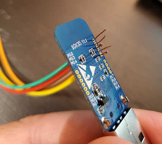
This is the trickier step of the process, as you need to do some delicate connections. You can start by carefully prying up the plastic enclosure from the USB dongle, so you can have access to the GPIO - five small holes to the left of the chip, labelled from top to bottom with the letters G, R, C, D and V.
Now you need to use 5 Dupont wires to connect the CC Debugger to the Zigbee stick. On the CC Debugger side, you have male pins, so you need to use a female end of the wires. On the following picture, notice the open slot on the left side:
The slot is also visible to the left of the pin 5 on the following connection guide, so you can use it to make sure you are reading the diagram with the proper orientation:

This diagram shows the wires coming from the CC Debugger pins (numbers) to the GPIO connectors (letters) as follows, following the GPIO positions from top to bottom:
1 → G
7 → R
3 → C
4 → D
2 → V
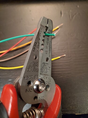
The connection on the CC Debugger side is easy, as you just connect the female end of the wires to the male pins. On the USB stick side, however, the connectors are very small and the male end of Dupont wires are too thick to enter into the holes. You may solder the wire ends to keep the connections in place, but if you don’t have tools and skills for that, you may find it simpler to follow what I did - strip the wires:
You can then pass the exposed wires through the GPIO holes, but you may want to use the following trick: once you have cut the wire sheathing, don’t pull it off with a straight movement; instead, while you pull the sheathing off the wire, keep twisting it around the axis of the wire to keep the strands tightly together. This is important to help keep the strands closely together, it is much more difficult to stick them through the tiny GPIO holes if the wire strands are scattered:
If you did it carefully enough, you can connect the wires in the right positions and make sure they do not touch each other:
Now you have the CC Debugger and the USB stick connected to each other, you then need to connect both to your computer to power them. The CC Debugger has a LED that may initially be red, but you can press its Reset button and if all your connections are properly in place the light will turn green:
Flashing the firmware
With the CC Debugger connected and powered on, Windows will recognize it but you will need to update the Cebal drivers previously downloaded from TI’s website. Open the Device Manager:
Look for the respective device, then right-click on it and manually install the driver files from the “win_64bit_x64” directory. You are now ready to install and open the SmartRF Flash Programmer.
By installing the right drivers, you will be able to see the CC Debugger on the first list just below the “System-on-Chip” tab. You need to select it, then search for the firmware file location on “Flash image”, and make sure that “Retain IEEE address when reprogramming the chip” is unchecked.
Ready to go! With “Erase, program and verify”, click on “Perform actions” and after some seconds your firmware should be written to the chip and verified.
Now you can disconnect the wires and USB connections, put the plastic case back on the Zigbee stick and then it is ready to be used as your Zigbee controller.
Zigbee binding configuration
Make sure that the Zigbee binding is installed and plug the CC2531 stick into the Raspberry Pi. You need to determine the device path assigned to your stick. If it is on /dev/ttyACM0, if you run udevadm info --query=all --name=/dev/ttyACM0 | grep "ID_MODEL=" you should have the following output:
E: ID_MODEL=TI_CC2531_USB_CDC
As mentioned in the binding documentation, “If you are running on Linux, then you probably need to add the user ‘openhab’ to the tty group, and enable EXTRA_JAVA_OPTS for the serial port your coordinator uses”. Search for “EXTRA_JAVA_OPTS” here in the forum if you need clarification on how to configure that.
You can then add a new Thing for the ZigBee binding. Select “CC2531EMK Coordinator” from the list (you may need to add it manually if the stick is not detected automatically) and on the “Port” field select the correct device path for your TI_CC2531_USB_CDC as verified above (/dev/ttyACM0, /dev/ttyACM1, /dev/ttyAMA0, etc).
After a couple of minutes, your coordinator should appear as Online in the list of Things. If needed, check the manual of your Zigbee end device to learn how to put it in pairing mode. Now, once you trigger a search for new Things for the ZigBee binding, it will put your coordinator in pairing mode for 60 seconds. You have this time to put your end device in pairing mode, so the coordinator will find it and the binding will recognize it as a new Thing of type “ZigBee Device”. Now you should be able to see the supported channels for your device and use them on your home automation!


