Hi trying to undersatnd how do i control this cheap valve
i have no expraince with motors , but i am working with tasmota for sonoff and other IOT stuff
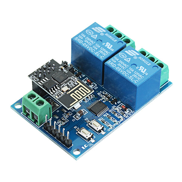
ok so got myself this arm valve
and when i apply 12V+ it goes one way
and when i apply 12V- it goes the other…
MDAR
(Stuart Hanlon, UK importer of Velbus hardware)
3
Hi
I don’t know anything about Tasmote, but I do know about DC motors.
In short, yes, you’ll need at least 2 relays.
However, they will both need to be
Single pole, double throw
And wired in a precise manner.
Connect each connection of the motor to the COM connection of a relay.
Connect the NC (Normally Closed) connection of BOTH relays to 0V
Connect the NO (Normally Open) connection of BOTH relays to +12V
Only 1 relay should be operated at a time, however, should both relays be triggered by mistake, nothing will happen or get damaged, simply because the potential difference across the motor will still be 0V (as in, 12V on one side and 12V on the other. 12 - 12 = 0)
Mode of operation
Operate Relay 1 for 10 seconds - motor will rotate in a direction for 10 seconds
Operate Relay 2 for 10 seconds - motor will rotate in the opposite direction for 10 seconds
Operate BOTH relays at the same time - nothing will happen
This method is fine for small motors, if you ever did this with a large motor, you would need to make allowances for dissipating the electrical energy created from the generation effect of the motor still rotating when power is removed (and the two connections being “shorted together, forming an electrical brake”, this can be done by applying a dummy load.)
I’m slowing venturing into MQTT with ESP-01 / ESP8266 boards.
If I were to need a solution like this, I would probably use
a ESP-01 with 2 relays
Simple Arduino project that listened to an MQTT topic for
** forward
** backward
** off
And trigger the two relays accordingly.
Thankfully, someone somewhere has already thought of this setup, so a quick search will return you things like this.
{FYI, these are Single Pole, Double Throw (SPDT) relays, so will work perfectly}
Does your valve have limit switches, so that you know when it has traveled to the end?
Once you have the motor relays working, you will probably have to think about timing elements, to shut off the motor after a while.
Hi @rossko57 i am not sure what is a limit switch, but i can hear that the motor stops working after it has reached the desierd place
but i am planing to make some kind of logic that will restore it to its orginal state(OFF)
in tasmota you can setup rules , that will run in the ESP even if no wifi conncted, so i think i will start there … if not i will do it in node red
and maybe you have an exmpale sketch for me?
i never done arduino… yet…
do you think that a framware like tasmota can do the same as the sketch ?
or maybe i will ask it a litle diffrently, Single Pole, Double Throw (SPDT) is done in the relay board or on the sketch ?
MDAR
(Stuart Hanlon, UK importer of Velbus hardware)
9
Sure, I’m happy to share what I’ve learnt so far.
When I get back to my office, I’ll post something on here.
MDAR
(Stuart Hanlon, UK importer of Velbus hardware)
10
Hello
I’ve had a play around with an ESP01 I have here and come up with a kind of controllable 2 relay setup.
I can’t get the “STOP” command to interrupt the DoAction loop, but I’m sure it’s only something small that I’ve missed.
(It’ll give you something to fix) Update, it was bugging me so I changed my approach, see 2nd script below
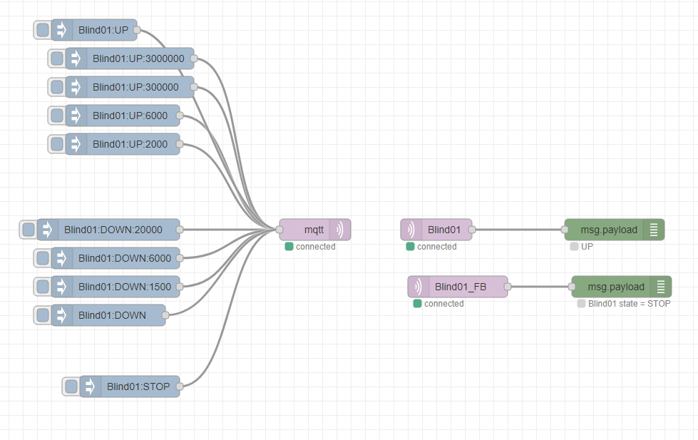
This is the Node-RED flow I use to control it with MQTT
Command structure I’ve used is -
Command:Duration in Milliseconds
IE
UP:5000 = UP for 5000ms DOWN:1500 = Down for 1500ms
STOP = ALL STOP, regardless of current state
UP = UP with a default duration of 500ms DOWN = DOWN with a default duration of 500ms
And this is the Arduino script I use on the ESP8266 / ESP01 board
#include "EspMQTTClient.h"


 #define Identifier "Blind01" // Delimiter is "_"

/* Which software GPio Pin to use (not the same as marked on board)

ESP01 = Pin 2 or 0
NodeMCU = Pin 5
*/

int UP = 2;
int DOWN = 0;


// MQTT client setup example

EspMQTTClient client(
  "WifiSSID",
  "WifiPassword",
  "192.168.1.100",  // MQTT Broker server ip
//  "MQTTUsername",   // Can be omitted if not needed
//  "MQTTPassword",   // Can be omitted if not needed
  Identifier,     // Client name that uniquely identify your device, as set above
//  1883              // The MQTT port, default to 1883. this line can be omitted
 );


int ind1;
int ind2;
String Command = "OFF" ;
String Duration = "500" ;
int Event;


volatile int state = false;
volatile int flag = false;
String input_state = "OFF";
String LEDState = "System Boot";


void ICACHE_RAM_ATTR changeStatus ();

unsigned long previousMillis = 0;
const long interval = 150;


void setup() {

      Serial.begin(9600);
    delay(2000);


      Serial.println("LED Setup....");
     pinMode(UP,OUTPUT);
     pinMode(DOWN,OUTPUT);

    digitalWrite(UP, LOW);
    digitalWrite(DOWN, LOW);
        delay(350);
    digitalWrite(UP, HIGH);
    digitalWrite(DOWN, LOW);
        delay(350);
        digitalWrite(UP, LOW);
    digitalWrite(DOWN, LOW);


    delay(2000);

          Serial.println("2nd Blink ....");

    digitalWrite(UP, LOW);
    digitalWrite(DOWN, LOW);
        delay(350);
    digitalWrite(UP, HIGH);
    digitalWrite(DOWN, LOW);
        delay(350);
        digitalWrite(UP, LOW);
    digitalWrite(DOWN, LOW);


    Serial.println("Preparing MQTT Relay control project...");


    Serial.println();
    Serial.println();
    Serial.print("Connecting to MQTT broker ");


      WiFi.mode(WIFI_OFF);        //Prevents reconnection issue (taking too long to connect)
       delay(1000);
      WiFi.mode(WIFI_STA);        //This line hides the viewing of ESP as wifi hotspot
                                   //WIFI_STA It's very important !!!!


    Serial.println("");
    Serial.println("No 5 is alive");


}


void onConnectionEstablished() {

  client.subscribe(Identifier, [] (const String &payload)  {
    Serial.println(payload);
      ind1 = payload.indexOf(':');  //finds location of first ,
 Command = payload.substring(0, ind1);   //captures first data String
      ind2 = payload.indexOf(':', ind1+1 );   //finds location of second ,
 Duration = payload.substring(ind1+1, ind2);   //captures second data String

 if ( Command != "UP" || Command != "up" || Command != "DOWN" || Command != "down"|| Command == "STOP"|| Command == "stop"|| payload == "STOP"|| payload == "stop"){
        digitalWrite(UP, LOW); // Change these to HIGH if your relays work that way
        digitalWrite(DOWN, LOW);
        client.publish(String(Identifier)+ "_FB", String(Identifier)+ " state = STOPPED");
        Event = 0; // Reset event so that a new message can overide this
                     };


 if ( Command == "UP" || Command == "up" || Command == "DOWN" || Command == "down"){

        Event = 1; // Triggers DoAction timer loop

                  }


  }

); // End of Subscribe loop

  client.publish(String(Identifier)+ "_FB", String(Identifier)+ " state = " + Command);
//  client.publish(String(Identifier), String(Identifier)+ " is Alive");


}


void loop() {
  client.loop();
  DoAction();
}


void DoAction(){

if (Event >0){

 if ( Command == "UP" || Command == "up"){
        digitalWrite(UP, HIGH); // Change these to HIGH or LOW according to how your relays work
        digitalWrite(DOWN, LOW);
 }


 if ( Command == "DOWN" || Command == "down"){
        digitalWrite(UP, LOW); // Change these to HIGH or LOW according to how your relays work
        digitalWrite(DOWN, HIGH);

 }
   client.publish(String(Identifier)+ "_FB", String(Identifier)+ " state = " + Command + ": Time = "+ Duration.toInt());

 if (!Duration){
  Duration = "5000"; // Sets a default duration if none is in the message
 }


delay(Duration.toInt()); // Durations of delay set by message
        digitalWrite(UP, LOW); // Change these to HIGH or LOW according to how your relays work
        digitalWrite(DOWN, LOW);
        client.publish(String(Identifier)+ "_FB", String(Identifier)+ " state = STOP");
   Event = 0; // Reset event so that a new message can overide this

}


}
Good luck, if you fix the STOP command, please do share how you manage it
This might help
Update
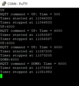
Well that didn’t take very long, I must be slowly learning things.
This version of the script (which uses a Time Check routine rather than a Delay command (Which seems to mean “Stop doing everything”) enables the STOP command.
#include "EspMQTTClient.h"


 #define Identifier "Blind01" // Delimiter is "_"

/* Which software GPio Pin to use (not the same as marked on board)

ESP01 = Pin 2 or 0
NodeMCU = Pin 5
*/

int UP = 2; // UP Relay connected to GPio No. (Which is not always the same as marked on the board)
int DOWN = 0; // DOWN Relay connected to GPio No. (Which is not always the same as marked on the board)

// If your relay board is inverted, just go through this Script and swap HIGH for LOW etc


// MQTT client setup example

EspMQTTClient client(
  "WifiSSID", // Your 2.4Ghz WiFi SSid
  "WifiPassword",  // Your WiFi password
  "192.168.1.100",  // MQTT Broker server ip
//  "MQTTUsername",   // Can be omitted if not needed
//  "MQTTPassword",   // Can be omitted if not needed
  Identifier,     // Client name that uniquely identify your device, as defined above
//  1883              // The MQTT port, default to 1883. this line can be omitted
 );


int ind1;
int ind2;
String Command = "OFF" ;
String Duration = "500" ;
bool Event;
bool Timer;


unsigned long currentMillis = 0;    // stores the value of millis() in each iteration of loop()
unsigned long previousMillis = 0;   // will store last time an action happened


void setup() {

      Serial.begin(9600);
    delay(2000);


      Serial.println("LED Setup....");
     pinMode(UP,OUTPUT);
     pinMode(DOWN,OUTPUT);

    digitalWrite(UP, LOW);
    digitalWrite(DOWN, LOW);
        delay(350);
    digitalWrite(UP, HIGH);
    digitalWrite(DOWN, LOW);
        delay(350);
        digitalWrite(UP, LOW);
    digitalWrite(DOWN, LOW);


    delay(2000);

          Serial.println("2nd Blink ....");

    digitalWrite(UP, LOW);
    digitalWrite(DOWN, LOW);
        delay(350);
    digitalWrite(UP, HIGH);
    digitalWrite(DOWN, LOW);
        delay(350);
        digitalWrite(UP, LOW);
    digitalWrite(DOWN, LOW);


    Serial.println("Preparing MQTT Relay control project...");


    Serial.println();
    Serial.println();
    Serial.print("Connecting to MQTT broker ");


      WiFi.mode(WIFI_OFF);        //Prevents reconnection issue (taking too long to connect)
       delay(1000);
      WiFi.mode(WIFI_STA);        //This line hides the viewing of ESP as wifi hotspot
                                   //WIFI_STA It's very important !!!!


    Serial.println("");
    Serial.println("No 5 is alive");


}


void onConnectionEstablished() {

  client.subscribe(Identifier, [] (const String &payload)  {
    Serial.println(payload);
      ind1 = payload.indexOf(':');  //finds location of first ,
 Command = payload.substring(0, ind1);   //captures first data String
      ind2 = payload.indexOf(':', ind1+1 );   //finds location of second ,
 Duration = payload.substring(ind1+1, ind2);   //captures second data String

 if ( Command == "STOP"|| Command == "stop"|| payload == "STOP"|| payload == "stop"){
        digitalWrite(UP, LOW); // Change these to HIGH if your relays work that way
        digitalWrite(DOWN, LOW);
        client.publish(String(Identifier)+ "_FB", String(Identifier)+ " state = STOPPED");
        Serial.println("Stopped by MQTT command at " + String(currentMillis));
        Event = false; // Reset event so that a new message can overide this
        Timer = false; // Cancel timer
                     };


 if ( Command == "UP" || Command == "up" || Command == "DOWN" || Command == "down"){
 //       Serial.println("MQTT command " state = " + Command + ": Time = "+ Duration.toInt());
        Event = true; // Triggers DoAction timer loop

                  }


  }

); // End of Subscribe loop

  client.publish(String(Identifier)+ "_FB", String(Identifier)+ " state = " + Command);
  client.publish(String(Identifier), String(Identifier)+ " is Alive");


}


void loop() {

   currentMillis = millis();   // capture the latest value of millis()
                             //   this is equivalent to noting the time from a clock
  client.loop();
  DoAction();
  TimerAction();
}


void DoAction(){

if (Event){


 if (Duration.toInt() == 0){
  Duration = "500"; // Sets a default duration if none is in the message
 }


 if ( Command == "UP" || Command == "up"){
        digitalWrite(UP, HIGH); // Change these to HIGH or LOW according to how your relays work
        digitalWrite(DOWN, LOW);
 }


 if ( Command == "DOWN" || Command == "down"){
        digitalWrite(UP, LOW); // Change these to HIGH or LOW according to how your relays work
        digitalWrite(DOWN, HIGH);


 }

         Serial.println("MQTT command = " + Command + ": Time = "+ Duration.toInt());

         client.publish(String(Identifier)+ "_FB", String(Identifier)+ " state = " + Command + ": Time = "+ Duration.toInt());

 if (!Duration){
  Duration = "5000"; // Sets a default duration if none is in the message
 }

        previousMillis = currentMillis; // Store point in time when action occured
        Event = false;
        Timer = true; // Start timer
            Serial.println("Timer started at " + String(currentMillis));
}


}


void TimerAction(){
  if (Timer) {
  if (currentMillis - previousMillis >= Duration.toInt()) {

    Serial.println("Timer stopped at " + String(currentMillis));
        Timer = false;
        digitalWrite(UP, LOW); // Change these to HIGH or LOW according to how your relays work
        digitalWrite(DOWN, LOW);
        client.publish(String(Identifier)+ "_FB", String(Identifier)+ " state = STOP");

  }


  }

}
MDAR
(Stuart Hanlon, UK importer of Velbus hardware)
11
Hi
That’s a phrase used to describe the physical characteristics of a relay.
For example.
A relay that only closes a single circuit would be called a “Single Pole, Single Throw”
Whereas a relay that offers TWO states, because the COM connection in it’s relaxed state connects to “Normal Closed” and in it’s energises state connects to “Normally Open”, would be called a “Single Pole, Double Throw”
For a DC inverter circuit, where both relaxed relays provide a kind of Electrical Brake (by effectively shorting out the motor) would be connected like this :-
(this diagram uses “Double Pole, Double Throw” relays, because that’s what I have in the image library)
I have no idea… I’ve never used the Tasmota firmware.
All I can tell you is that the script I’ve written prevents both relays being ON at the same time.
(not a major issue with this diagram and style of DC polarity control, but it would be fatal for a MAINS blind motor, should 2 x LIVE be applied at the same time, I know because I’ve done it… ONCE)
IE
The UP command
Switches ON the UP relay and ensures the DOWN relay is OFF
The DOWN command
Switches ON the DOWN relay and ensures the UP relay is OFF
The STOP command simply switches OFF both relays
BE AWARE
The relay board you have purchased uses a serial connection to the ESP01, NOT the GPIO pins.
As hinted at here