Use case:
I’m using a Gardena smart irrigation control (with 6 separate water cycles) to water my yard, fed by the tab and a cistern. After one year I realized I have no clue how much water is being consumed. In the forum here, here and here, solutions were discussed, but these sensors were either expensive or difficult to get. There are also reasonably priced sensors (e.g. this one), but the long battery life comes at the expense of a rather long measurement intervals (3 hours) and the necessity of a LoRaWAN gateway.
Goal:
Be able to place cheap “real-time” water flow sensors around the house for full transparency on the water consumption of various consumers, and for being able to send alarm messages to my mobile in case odd water consumption profiles are being detected (e.g. “more than x00 liters in y hours”, e.g. when a water hose burst).
Effort:
Two afternoons of fun, tinkering, and lots of learning on MQTT, hall sensors and ESP scripting.
Hardware used:
- Raspi 3B+ running openHAB 3.3
- I’m using the YF-B5 flow sensor (3/4") for ~€ 10 per piece and the YF-B10 flow sensor (1") for ~ €21 per piece. They’re probably not as precise as really expensive sensors (see below), but they get the job done.
- One ESP-WROOM-32 (< € 10).
Working principle of the sensors:
The working principle of the sensor is important to understand. The reason why the YF-B5 and the YF-B10 are so cheap is because they’re basically just a metal pipe with a polymer / injection-moulded turbine in it. On two blades of the turbine is a small piece of metal. When the turbine turns, it triggers the hall sensor in the black box on top of the sensor.

Step 1: Flashing Tasmota on the ESP
- Connect a USB cable (be careful to not get a “power-only” cable, but one that also carries data) to the micro USB-port of the ESP.
- Since a Tasmota version with “Script” instead of “Rules” is needed, either compile it yourself or download it here (ESP32) or here (ESP8266). I did the latter, which worked fine.
- For the actual flashing, either use the web tool under this link (also works under Linux, but both in Linux or Windows Chrome has to be used) or download and install Tasmotizer.
- After you’re done flashing, use Tasmotizer to send the WiFi-details (SSID and Password) to the ESP.
- Afterwards you should be able to get the IP address of the ESP either via your router or via Tasmotizer (“Get IP Address”). At this point you can unplug the ESP from your computer and just use a standard USB power supply.
- Now you should be able to access the ESP / Tasmota GUI by entering the IP address into your browser.
If the programming of the ESP with Tasmota does not work, try…
- using a different USB port on your computer
- using a different USB cable (some cables only support power, not data)
- switching from Tasmotizer to the web installer (or vice versa)
Step 2: Connect the sensor
- Since it can take some trial-and-error to get the sensor to work, mounting the ESP on a breadboard is a good idea.
- Cut off the black plastic plug of the sensor.
- Connect “Red” to “3V”, “Black” to “G” and Yellow (the impulse of the turbine) to an input channel of the ESP (in my case: “Input 14”).

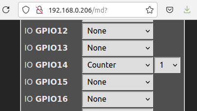
Step 3: Configure Tasmota
- Enter the ESP’s IP address into your browser.
- Under “Configuration” → “Configure Module” give Tasmota the information where to get the counter signal from (here: on channel 14).
Step 4: Import the script that converts “turbine ticks” into “water”
As mentioned above, the sensor just sends “ticks” to the ESP. The trick is to convert these ticks into “water flown through in between two ticks”.
One possibility to do so doing the conversion in openHAB. However, more “real-time” is doing the conversion on the ESP itself. This can be done with with the Tasmota Scripting language, which looks a bit crude, but appears to be very efficient.
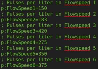
A good version of a script that does that can be found here. I took this script as a basis and did some further editing to it (incl. more intervals, see below, and more documentation in the code itself, in case I have to edit it in a couple of months from now). My documentations might help you as well.
>D
; A valid script must start with >D in the first line
; Reference see here: https://tasmota.github.io/docs/Scripting-Language/

; Variables are defined and initialized (p means permanent)
; Total number of counted pulses
p:TotalPulses=0
; Total number of measured liters
p:TotalLiter=0
; Pulses per liter in Flowspeed 1
p:FlowSpeed1=150
; Pulses per liter in Flowspeed 2
p:FlowSpeed2=183
; Pulses per liter in Flowspeed 3
p:FlowSpeed3=420
; Pulses per liter in Flowspeed 4
p:FlowSpeed4=275
; Pulses per liter in Flowspeed 5
p:FlowSpeed5=350
; Pulses per liter in Flowspeed 6
p:FlowSpeed6=375
; Upper threshold for Flowspeed 1 (in Pulse/second)
p:FlowSpeed1TC=2
; Upper threshold for Flowspeed 2 (in Pulse/second)
p:FlowSpeed2TC=5
; Upper threshold for Flowspeed 3 (in Pulse/second)
p:FlowSpeed3TC=10
; Upper threshold for Flowspeed 4 (in Pulse/second)
p:FlowSpeed4TC=25
; Upper threshold for Flowspeed 5 (in Pulse/second)
p:FlowSpeed5TC=75
; Variable for reset button
resetb=0
; Number of pulses in timer period (in Pulses/second)
PulseRate=0
; Flow rate in current timer period (in Liter/min)
FlowRate=0
; Temp variable for amount of water flown through in current timer period (in liter)
tmp=0
; Current water flow in current timer period (string: high, medium or low)
cflow="none"

>B
; >B is executed on BOOT time before sensors are initialized and on save script
; After boot restore "total number of counted pulses" back to latest state of ESP pulse counter 1 (pc[1])
TotalPulses=pc[1]

>S
; >S is executed every second
; If reset button resetb has been pushed (resetb has been set to 1)
if resetb==1
then
; The reset button variable resetb is set back to 0
resetb=0
; The total number of counted pulses is set back to 0
TotalPulses=0
; The total number of counted liters is set back to 0
TotalLiter=0
; ESP variable counter1 is set back to 0
=>Counter1 0
endif

; Calculation of number of pulses in past 1 second ("PulseRate")
; PulseRate = Total # of Pulses from ESP Counter - Total # of Pulses one second ago
PulseRate=pc[1]-TotalPulses
; Afterwards, total # of pulses one second ago is set to Current total # of Pulses from ESP Counter
TotalPulses=pc[1]

; Determination of Flowspeed Cluster (1 to 6) and amount of water flown through (in liter) in past 1 second
; If "# of pulses in timer period" greater than "upper threshold for respective flowspeed cluster"
if PulseRate>FlowSpeed5TC
then
; Set current flow variable (cflow, string for text output) to the respective flowspeed
cflow="Flowspeed6"
; Calculate the current water flown through in past 1 second by dividing the "number of pulse counts" (PulseRate) by "pulses per liter for respective Flowspeed"
tmp=(PulseRate/FlowSpeed6)
endif

if PulseRate<FlowSpeed5TC
and PulseRate>FlowSpeed4TC
then
cflow="Flowspeed5"
tmp=(PulseRate/FlowSpeed5)
endif

if PulseRate<FlowSpeed4TC
and PulseRate>FlowSpeed3TC
then
cflow="Flowspeed4"
tmp=(PulseRate/FlowSpeed4)
endif

if PulseRate<FlowSpeed3TC
and PulseRate>FlowSpeed2TC
then
cflow="Flowspeed3"
tmp=(PulseRate/FlowSpeed3)
endif

if PulseRate<FlowSpeed2TC
and PulseRate>FlowSpeed1TC
then
cflow="Flowspeed2"
tmp=(PulseRate/FlowSpeed2)
endif

if PulseRate<FlowSpeed1TC
and PulseRate>0
then
cflow="Flowspeed1"
tmp=(PulseRate/FlowSpeed1)
endif

; If no pulses have been counted in past 1 second...
if PulseRate==0
then
; The current water flow-string is set to "none"
cflow="none"
; The amount of water flown through in past 1 second is set to 0 liter
tmp=0
endif

; Calculate total amount of water (in liter)
; The new total amount of water (in liter) is calculated with the previous amount (in liter) plus the new amount in the past 1 second
TotalLiter=(TotalLiter+tmp)
; The flow rate (in Liter/min) in the past 1 second is calculated by multiplying the amount of water in the timer period (tmp) * 60 seconds
FlowRate=tmp*60


; Every 60 seconds: Print status, save permanent variables and publish via MQTT
if upsecs%60==0
then
; Print a summary in the tasmota log
print Status: Flowrate (in liter/min): %FlowRate%, Total (in liter): %TotalLiter%, Total (in pulses): %TotalPulses%, Pulsesrate (in pulses/sec): %PulseRate%
; save permanent vars (see p: above)
svars
=>publish stat/%topic%/Flow {"FlowRate":%FlowRate%,"TotalLiter":%TotalLiter%,"TotalPulses":"%TotalPulses%","PulseRate":%PulseRate%}
endif

>W
; The lines in the >W section are displayed in the web UI main page.

; Total number of measured liters (in liter)
Total{m}%TotalLiter% Liter
; Flow rate in current timer period (in Liter/min)
Flow Rate{m}%FlowRate% Liter/min
; Pulse rate in current timer period (in Pulse/sec)
Pulse Rate{m}%PulseRate% Pulse/sec
; Current water flow in current timer period (high, medium or low)
Flowspeed Cluster{m}%cflow%

; Upper threshold (in pulses per second) for different flowspeed clusters
; Number Inputs (min, max, step, variable name, label text, horizontal size)
nm(0 400 1 FlowSpeed1TC "Upper threshold for Flowspeed 1 (in Pulse/Sec) " 80)
nm(0 400 1 FlowSpeed2TC "Upper threshold for Flowspeed 2 (in Pulse/Sec) " 80)
nm(0 400 1 FlowSpeed3TC "Upper threshold for Flowspeed 3 (in Pulse/Sec) " 80)
nm(0 400 1 FlowSpeed4TC "Upper threshold for Flowspeed 4 (in Pulse/Sec) " 80)
nm(0 400 1 FlowSpeed5TC "Upper threshold for Flowspeed 5 (in Pulse/Sec) " 80)

; Flowspeed (in pulses per liter) for different flowspeed clusters
; Number Inputs (min, max, step, variable name, label text, horizontal size)
nm(0 1000 1 FlowSpeed1 "Flowspeed 1 (in Pulse/liter) " 80)
nm(0 1000 1 FlowSpeed2 "Flowspeed 2 (in Pulse/liter) " 80)
nm(0 1000 1 FlowSpeed3 "Flowspeed 3 (in Pulse/liter) " 80)
nm(0 1000 1 FlowSpeed4 "Flowspeed 4 (in Pulse/liter) " 80)
nm(0 1000 1 FlowSpeed5 "Flowspeed 5 (in Pulse/liter) " 80)
nm(0 1000 1 FlowSpeed6 "Flowspeed 6 (in Pulse/liter) " 80)

; Button (variable name, text of ON state of button, text of OFF state of button)
bu(resetb "Resetting" "Reset Total")
The script basically converts “# of ticks in a timeframe” into “water flown through in the same timeframe”. Unfortunately, the “# of ticks per amount of water” is not constant over the “flowspeed”, probably because it is a really cheap sensor. To compensate for that, the script above distinguishes six different flow speeds (precise enough for me), ranging from “2 pulses per second” (water only dripping through) up to “75 pulses per second” (full speed).
Copy your version of script into the window “Console” → “Edit Script” (not “Berry Scripting Console”) and activate the checkbox “Script enable”.

Afterwards the Tasmota main menu should look like this:

Step 5: Calibrate the sensor (optional, if using the YF-B5)
This part can be tricky / take some time. You can of course take my calibration values, but I assume that even two sensors of the same production batch can have variations, let alone the bigger YF-B10 sensor. So I’d recommend to at least cross-check my values.
To calibrate the sensor, let one liter of water flow through the sensor at the respective speed, and enter the number of pulses counted into the script under the respective flowspeed. The reset-button helps resetting the counters. For comfort reasons, the numbers can also be entered in the field in the main menu, but to be safe (after restart) it is better to include the values in the code itself.
Step 6: Enable openHAB to receive the flow information
Assuming that MQTT is already working on your openHAB installation (if not, here under #3 are some hints), the goal is to create an openHAB item which receives the information from the ESP.
- Create a thing for the ESP and various channels that capture the water flow and other telemetry information from the ESP. In my case this finally looked like this. Please note that the ID of the MQTT-bridge (
7519737e0f) needs to be replaced by the openHAB ID of your MQTT-bridge.
UID: mqtt:topic:7519737e0f:flow_meter_1
label: Flow Meter 1
thingTypeUID: mqtt:topic
configuration: {}
bridgeUID: mqtt:broker:7519737e0f
location: Garten
channels:
  - id: counter
    channelTypeUID: mqtt:number
    label: Total number of pulses
    description: null
    configuration:
      postCommand: false
      retained: false
      step: 1
      formatBeforePublish: "%s"
      stateTopic: tele/flow_meter_1/SENSOR
      transformationPattern: JSONPATH:$.COUNTER.C1
  - id: temperature
    channelTypeUID: mqtt:number
    label: ESP32 core temperature
    description: null
    configuration:
      postCommand: false
      retained: false
      step: 1
      formatBeforePublish: "%s"
      stateTopic: tele/flow_meter_1/SENSOR
      transformationPattern: JSONPATH:$.ESP32.Temperature
  - id: time
    channelTypeUID: mqtt:string
    label: Local ESP32 time
    description: null
    configuration:
      postCommand: false
      retained: false
      step: 1
      formatBeforePublish: "%s"
      stateTopic: tele/flow_meter_1/SENSOR
      transformationPattern: JSONPATH:$.Time
  - id: uptime
    channelTypeUID: mqtt:string
    label: Uptime
    description: null
    configuration:
      postCommand: false
      retained: false
      step: 1
      formatBeforePublish: "%s"
      stateTopic: tele/flow_meter_1/STATE
      transformationPattern: JSONPATH:$.Uptime
  - id: UptimeSec
    channelTypeUID: mqtt:number
    label: Uptime (in seconds)
    description: null
    configuration:
      postCommand: false
      retained: false
      step: 1
      formatBeforePublish: "%s"
      stateTopic: tele/flow_meter_1/STATE
      transformationPattern: JSONPATH:$.UptimeSec
  - id: RSSI
    channelTypeUID: mqtt:number
    label: RSSI (in %)
    description: null
    configuration:
      postCommand: false
      retained: false
      step: 1
      formatBeforePublish: "%s"
      stateTopic: tele/flow_meter_1/STATE
      transformationPattern: JSONPATH:$.Wifi.RSSI
  - id: Signal
    channelTypeUID: mqtt:number
    label: Signal Strength (in db)
    description: null
    configuration:
      postCommand: false
      retained: false
      step: 1
      formatBeforePublish: "%s"
      stateTopic: tele/flow_meter_1/STATE
      transformationPattern: JSONPATH:$.Wifi.Signal
  - id: FlowRate
    channelTypeUID: mqtt:number
    label: Flow Rate (in liter/min)
    description: null
    configuration:
      postCommand: false
      retained: false
      step: 1
      formatBeforePublish: "%s"
      stateTopic: stat/flow_meter_1/Flow
      transformationPattern: JSONPATH:$.FlowRate
  - id: TotalLiter
    channelTypeUID: mqtt:number
    label: Total amount (in liter)
    description: null
    configuration:
      postCommand: false
      retained: false
      step: 1
      formatBeforePublish: "%s"
      stateTopic: stat/flow_meter_1/Flow
      transformationPattern: JSONPATH:$.TotalLiter
  - id: TotalPulses
    channelTypeUID: mqtt:number
    label: Total amount of pulses
    description: null
    configuration:
      postCommand: false
      retained: false
      step: 1
      formatBeforePublish: "%s"
      stateTopic: stat/flow_meter_1/Flow
      transformationPattern: JSONPATH:$.TotalPulses
  - id: PulseRate
    channelTypeUID: mqtt:number
    label: Pulse rate (in pulses/second)
    description: null
    configuration:
      postCommand: false
      retained: false
      step: 1
      formatBeforePublish: "%s"
      stateTopic: stat/flow_meter_1/Flow
      transformationPattern: JSONPATH:$.PulseRate
Please also note that the topic of your Tasmota device (in my case flow_meter_1) has to match whatever you have configured in Tasmota under “Configuration” → “MQTT Parameters” → “Topic”.

Afterwards you can use openHAB to visualize the information being recorded in the respective items.

Step 7: Install the flow sensor
Installing the sensor is not particularly difficult, but in the end harder than expected. With a simple “single-piece fitting” (as visible on the pic below) I could not get it to be tight.

What’s crucial is having a good fitting, e.g. one made from two parts. This one here worked great for me.

Closing remarks
As mentioned, the flow sensor used is not super precise. But for my purpose (get an impression on the amount of water consumed at various points around the house) good enough.
There’s another iteration which is rather neat: A colleague of mine used an ESP-01, which is small enough to be place in a 3D-printed housing that can be mounted on top of the flow sensor (the screws can be removed really easy).